The Truth About Ultra-Thin Heat Pipe Vapor Chambers
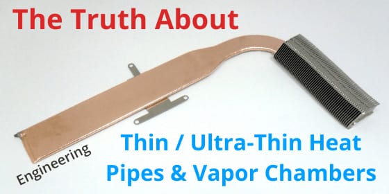
Thin and ultra-thin heat pipe vapor chambers offer excellent choices for space-constrained applications where heat needs to be moved to a remote location or spread quickly to a larger heat sink surface area. However, mechanical engineers should be mindful of the concessions that come with choosing these devices.
In this blog, we’ll break down the design variables of a heat pipe or vapor chamber, discuss each part’s purpose, and examine the implications of making each element thinner: enclosure wall thickness, wick thickness, wick type, vapor space, and internal support structures. Then, we’ll look at how each component can be changed to achieve a thinner device along with the performance impact of each change. Here, we’ll use the following definitions:
- Thin two-phase devices
- Heat pipes of thickness down to 1.1mm
- Vapor chambers of thickness down to 1.55mm
- Ultra-thin two-phase devices
- Heat pipes of thickness down to 0.6m
- Vapor chambers of thickness down to 1.3mm with some experimental designs reaching 0.2mm
Standard and Thin Heat Pipe Vapor Chamber Component Parts
Enclosure Wall Thickness
Whether made from copper (the most common), stainless steel, titanium or aluminum, a heat pipe’s enclosure wall is what gives it most of the strength needed to maintain structural integrity during nominal clamping forces of 20-60 psi against the heat source. While standard sintered wick copper heat pipes have a wall thickness between 0.1-0.3mm, vapor chamber walls are slightly thicker at between 0.3-0.5mm. The thicker walls along with an internal support structure allow vapor chambers to maintain structural integrity despite higher; aspect ratios.
Internal-Support Structure (vapor chamber only)
With sintered heat pipes, the width-to-height aspect ratio rarely exceeds 3:1 but for vapor chambers, we regularly produce parts with a 10 :1 ratio. The great advantage is that heat is spread in all directions over a large surface area. The disadvantage is that its structural rigidity against clamping force or accidental bump is diminished. To solve this problem, thicker walls and an internal support structure, usually in the form of vertical columns, are added to span the upper and lower divide of the internal enclosure walls. While support structures are designed to limit the reduction in vapor space, they often result in slightly reduced Qmax for many applications.
Vapor Space
The empty space inside the thin heat pipe vapor chamber enclosure is what allows the vaporized liquid to move to areas of lower pressure – and really what gives a two-phase device its potential to move high power density with very low thermal resistance. Round heat pipes, especially those diameters above 5mm, have enough excess vapor space that flattening them slightly has no effect on Qmax. However, after a certain flattening point, Qmax will start to decrease.
Wick Thickness & Type
Heat pipe wick thickness, structure, and type all play key roles in helping move the condensed liquid from the heat sink area to the heat source area so that the two-phase cycle can continue. If the device needs to operate against gravity (heat source above heat sink) you must have a wick. The most common, most efficient, and thickest is a sintered wick followed in all categories by bundled fiber, mesh and grooved/etched wicks. As heat pipe wick thickness increases, the amount of vapor space, in many cases, is diminished resulting in reduced thermal performance.
Thin Heat Pipe Vapor Chambers
When heat pipe vapor chamber performance and flatness across a wide range of power densities and orientations are needed, a sintered wick is likely a necessity. Typical configurations for sintered wicks include, a) attached all the way around the inner walls of a thin heat pipe and b) attached to both the upper and lower plates of a thin vapor chamber. This configuration circulates the most condensed liquid back to the evaporator, an especially important consideration for operation against gravity and/or with higher power density heat sources.
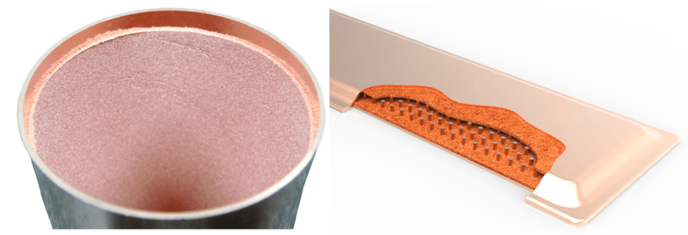
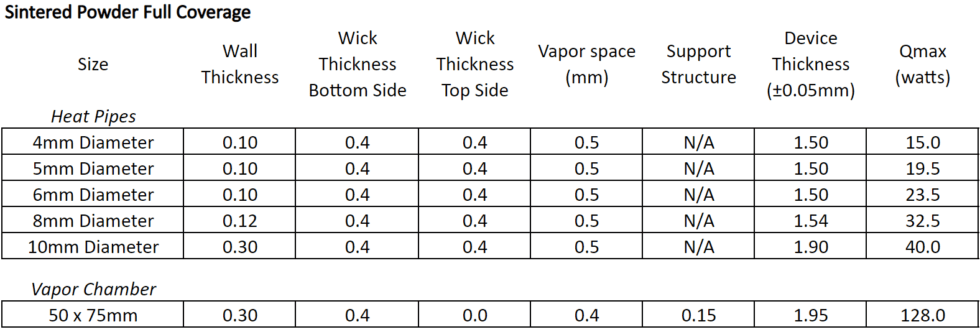
As seen in the table above, thin heat pipes and vapor chambers range in thickness from 1.5mm to nearly 2.0mm if a full coverage wick is required to ensure the most effective fluid return if the device is operating against gravity.
If power density, top heat pipe Qmax performance, and working against gravity are less of a concern, it’s possible to make a thinner device while keeping the same vapor space by applying the sintered wick to only the evaporator side of the device. For thin heat pipes, this means a sintered wick on slightly less than half the inner wall (before flattening) and for thin vapor chambers it means just the lower plate that contacts the evaporator will have a wick structure. See image below.
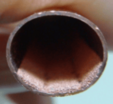
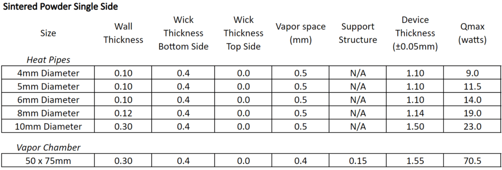
By removing the sintered wick on the top side of the thin heat pipe or vapor chamber, we’re able to reduce the overall device thickness by 0.4mm while maintaining the vapor space. In these cases, Qmax is reduced by almost half because the device is unable to return liquid to the evaporator even while operating in the horizontal orientation. An important consideration when reducing the amount of wick material is that Qmax will drop very fast as the device is required to work harder against gravity.
Ultra-Thin Heat Pipe Vapor Chambers
Further changes in wick structure and wall thickness are the only ways to manufacture ultra-thin heat pipes and vapor chambers. While sintered wicks allow for higher power densities (100’s of watts/sq cm2) and the ability to work against gravity, certain applications may not require these levels of performance. Let’s look at alternative wicks: bundled fiber and mesh.
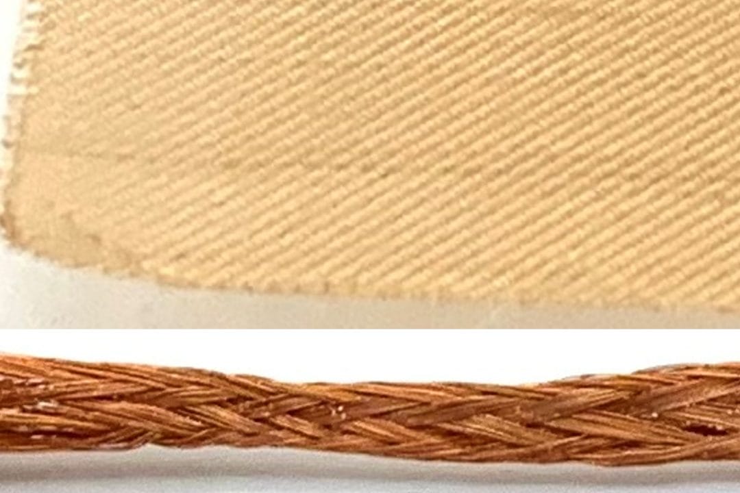
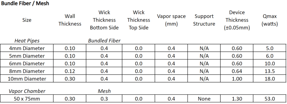
Mesh is often favored for vapor chambers, which are typically not bent, because it allows for greater design flexibility. The ultra-thin mesh screens have a variety of weaves to choose from as well as the ability to be used alone or in conjunction depending on the application. Further, if the device is operating with gravity (evaporator above condenser) or in the horizontal, mesh can allow for higher Qmax figures.
As we can see from the table below, we see ultra-thin heat pipes down to 0.6mm with vapor chambers achieving as little as 1.3mm.
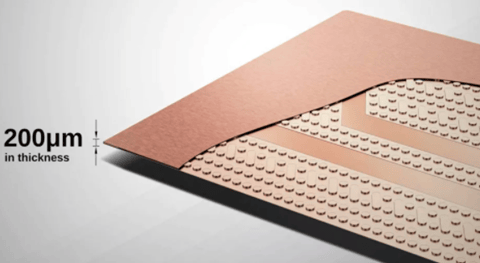
Choices for ultra-thin heat pipes and vapor chambers lead to high strength materials such as titanium or very low strength composites such as mylar/metal foil composites (image below). Both technologies have been around for decades but recently the need for spreading hot spots in low-powered consumer devices has led to the adoption of these ultra-thin, low-capacity devices.
Celsia is a custom heat sink manufacturer using vapor chamber and heat pipe technology. We specialize in: heat sink design, heat sink proto, heat sink manufacturing, heat pipes, vapor chambers, custom heat pipe wick materials.


