PCM Thermal Storage
As with most things aeronautical, a thermal solution’s weight and size play important roles in device selection. Traditional RF heat sinks (non-PCM) designed for use only while airborne or on winter tarmac will be smaller and lighter than ones designed for use on the ground at elevated ambient temperatures. The latter will require some combination of more base area, more fin area, additional airflow (fans), or a more thermally conductive material (copper vs aluminum). The result is likely a heat sink that is heavier, bigger, and considerably more costly.
The challenge then becomes one of designing the lightest and smallest heat sink for a duty cycle where 90% of its operational time is at very moderate or even cold ambient temperatures with only 10% of its time at elevated ambient temperatures – generally less than 90 minutes for this application. This is where phase change material comes into play.
Types of Phase Change Material (PCM)
There are 4 broad categories of PCM materials highlighted in the table below.
| Attribute / PCM Type |
Metallics |
Salt Hydrate | Plant-Based |
Paraffin Wax |
| Latent Heat (KJ/Kg) |
25 to 100 |
60 to 3000 | 90-250 |
150-280 |
| Thermal Conductivity |
High (~20) |
Low (0.6-1.2) | Very Low (0.20) |
Very Low (~0.25) |
| Corrosiveness |
Varies |
Corrosive | Mildly Corrosive |
Non-Corrosive |
| Toxicity |
Some Are |
Highly | Some Are |
No |
| Melt Temp (C) |
30 to 125 |
0 to 120 | 5 to 120+ |
-20 to 100+ |
| Thermal Cycling |
Stable |
Unstable over repeated cycles | Elevated temp can cause decomposition |
Stable |
| Weight |
Heavy |
Light | Medium |
Medium |
| Price |
Close to that of Plant Based |
Least Expense | Most Expensive |
Close to that of Salt Hydrate |
Of these, paraffin wax is the most widely used PCM for electronics cooling applications because of its high latent heat without the corrosivity, toxicity, and potentially unstable thermal cycling characteristics of other materials. Further, it’s available in melt temperatures that align nicely with electronics applications (20-100oC) while it scores well on weight and price attributes. The biggest drawback of paraffin wax is its very low thermal conductivity. A proper heat sink design must incorporate features to uniformly spread the heat into the paraffin.
Phase Change Material Heat Sink Design Elements
A heat sink that incorporates paraffin wax PCM for thermal storage in its simplest form looks very much like a standard heat sink. As seen in the image below, a fin structure optimized to maximize wax volume while providing enough fin area to adequately heat the low-conductivity paraffin is mounted to an aluminum base plate with six embedded heat pipes (optional for improved heat spreading). Next, the paraffin is added to an enclosure lid (not shown) and the fin side is pressed into it. Lastly, the enclosure is diffusion bonded to the base sealing the wax inside.
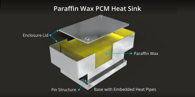
Paraffin Wax Phase Change Material Used to Cool Airplane Electronics
How Do PCM Heat Sinks Work?
Using our earlier example of an RF amplifier used to cool a commercial jet’s Wi-fi system, we can see just how these devices work. While airborne, ambient temperatures are quite cold resulting in a rather simple thermal challenge. The real challenge is typical during the 60 to 90 minutes aircraft are sitting at the gate, on the hot tarmac, in ambient temperatures up to 50°C. During this phase of the flight cycle the heat generated substantially exceeds the ability of the heat sink to expel the heat to air. By incorporating a paraffin PCM into the heat sink design, as the heat sink temperature rises to the melting point of the wax the phase change of the paraffin absorbs the heat.
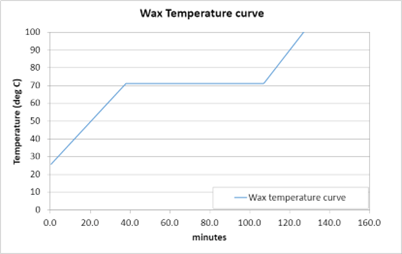
PCM Temperature Curve – Stable Wax Temperature Despite Increasing Ambient Temperature
This chart exhibits a typical prediction of the temperature profile of a heat sink that incorporates a PCM. The heat sink temperature rise is linear up until the point of the phase change and flat during the time it takes to fully melt the PCM. This particular PCM has a melting point of 72°C. The result of this type of heat sink design is a significantly smaller and lighter cooling solution than if the design was simply an air-cooled design.
Recommended Blog Posts
The Truth About Ultra-Thin Heat Pipe Vapor Chambers
Thin and ultra-thin heat pipe vapor chambers offer excellent choices for space-constrained applications where heat needs to be moved to a remote location or spread quickly to a larger heat sink surface area. However, mechanical engineers should be mindful of the...
Vapor Chamber vs Heat Pipe
Although based on the same inner working principles, heat pipes and vapor chambers have unique characteristics in terms of design, usage and integration.
How Do Heat Pipes Work | Heat Pipes 101
This article covers how heat pipes and vapor chambers work along with typical uses and configuration options. Further, it is designed to be a quick read with links to detailed information throughout the text. How Do Heat Pipes Work? There are three...
Heat Pipe Thermal Conductivity
Knowing heat pipe thermal conductivity is important when performing Excel or CFD modeling of two-phase devices integrated into a heat sink assembly. In theory, heat pipe thermal conductivity can range from 4,000 to 100,000 W/m-K. In reality, the range for electronics...

