Fundamentals of Thermal Resistance

Fundamentals of Thermal Resistance

Fundamentals of Thermal Resistance


Today’s guest blog on the fundamentals of thermal resistance is from Dr. James Stevens, Professor Mechanical Engineering at the University of Colorado. Dr. Stevens specializes in numerical and analytical heat transfer analysis covering both steady-state and transient situations with applications to thermal history, thermal response, electronic cooling, temperature profiles, thermal design, and heat flow rate determination.

The Thermal Resistance Analogy

Thermal resistance is a convenient way of analyzing some heat transfer problems using an electrical analogy in order to make complicated systems easier to visualize and analyze. It is based on an analogy with Ohm’s law which is:

Ohms Law

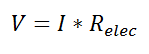
In Ohm’s law for electricity, “V” is the voltage which drives a current of magnitude “I”. The amount of current that flows for a given voltage is proportional to the resistance (Relec). For an electrical conductor, the resistance depends on the material properties (copper tends to have a lower resistance than wood, for example) and the physical configuration (thick short wires have less resistance than long thin wires).

pic2


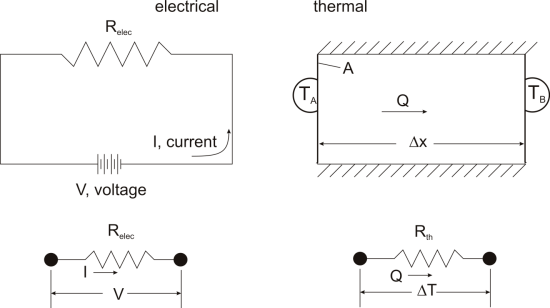
For one-dimensional, steady-state heat transfer problems with no internal heat generation, the heat flow is proportional to a temperature difference according to this equation:

pic3

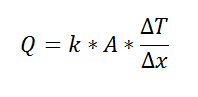
where Q is the heat flow, k is the material property of thermal conductivity, A is the area normal to the flow of heat, Δx is the distance that the heat flows, and ΔT is the temperature difference driving the heat flow.

If we create an analogy by saying that electrical current flows like heat, and saying that voltage drives the electrical current like the temperature difference drives the heat flow, we can write the heat flow equation in a form similar to Ohm’s law: pic4
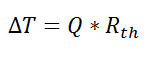
where Rth is the thermal resistance defined as: pic5
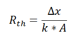
Just as with the electrical resistance, the thermal resistance will be higher for a small cross-sectional area of heat flow (A) or for a long distance (Δx).

Rationale

Now, why bother with all that? The answer is that thermal resistance allows us to solve somewhat complicated problems in relatively simple ways. We’ll talk more about different ways in which it can be used, but first let’s look at a simple case in order to illustrate the benefit.

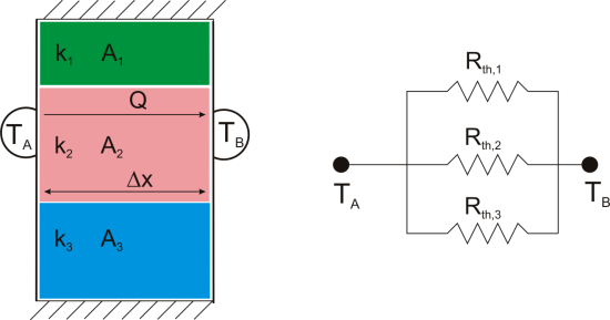
Suppose that we want to calculate the heat flow through a wall composed of three different materials, and we know the surface temperatures at each outside surface, TA, and TB, and the material properties and geometries.

pic6


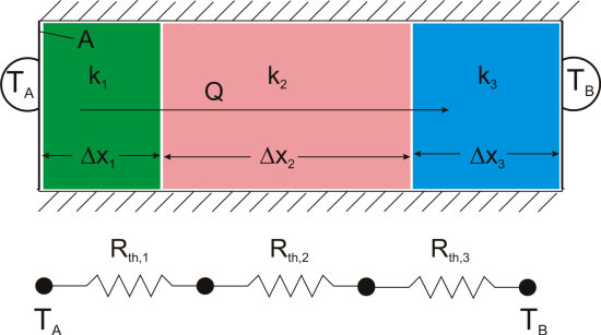
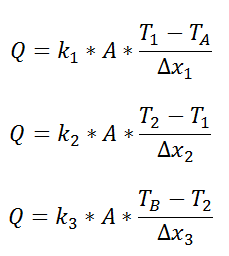
We could write the conduction equation for each material:

pic7


Now, we have three equations, and three unknowns: T1, T2, and Q. For this case it wouldn’t be too much work to algebraically solve for those three unknowns, however, if we use the thermal resistance analogy, we don’t even have to do that much work:

pic8

wherepic9

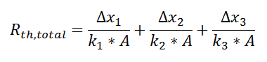
and we can solve for Q in a single step.

Combining Thermal Resistances

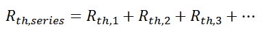
This simple example showed how to combine multiple thermal resistances in series which is the same structure as in the electrical analog:

pic10

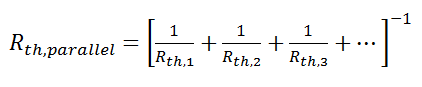
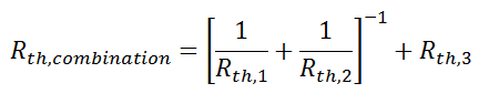
Just like electrical resistances, thermal resistances can also be combined in parallel, or in both series and parallel:

pic11

pic12

pic13

Beyond Conduction

So far, we’ve talked about the thermal resistance associated with conduction through a plane wall. For steady-state, one-dimensional problems, other heat transfer equations can be formulated into a thermal resistance format. For example, examine Newton’s Law of Cooling for convection heat transfer:

pic15

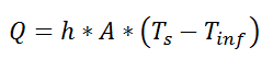
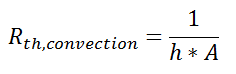
where Q is the heat flow, h is the convective heat transfer coefficient, A is the area over which heat transfer occurs, Ts is the surface temperature on which the convection is taking place, and Tinf is the free-stream temperature of the fluid. As with conduction, there is a temperature difference driving a heat flow. For this case, the thermal resistance would be:

pic16

Similarly, for radiative heat transfer from a gray body:

pic17

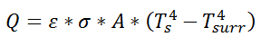
where Q is the heat flow, ε is the emissivity of the surface, σ is the Stefan-Boltzmann constant, Ts is the surface temperature of the emitting surface, and Tsurr is the temperature of the surroundings. By factoring the expression for temperature, the thermal resistance can be written: pic18

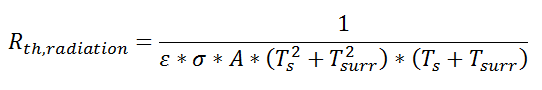
Advantage: Easy Problem Setup

Thermal resistance formulations can make the arrangement of a quite complex problem quite simple to set up. Imagine, for example, that we are trying to calculate the heat flow from a liquid stream of a known temperature through a composite wall to an air stream with convection and radiation occurring on the air side. If the material properties, heat transfer coefficients, and geometry are known, the equation set-up is obvious:


pic20


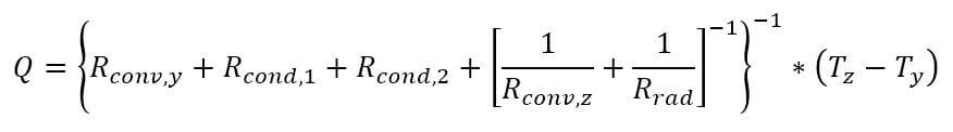
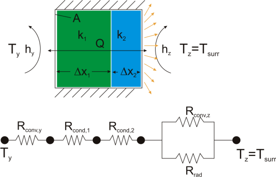
Now, to solve this particular problem might involve an iterative solution since the radiative thermal resistance contains the surface temperature inside of it, but the setup is simple and straightforward.

Advantage: Problem Insight

The thermal resistance formulation has the additional advantage of making it very clear which parts of the model are controlling the heat transfer, and which parts are unimportant, or perhaps even negligible. As a concrete illustration, let’s suppose that in the last example the thermal resistance on the liquid side was 20 K/W, that the first layer in the composite wall was 1 mm thick plastic with a thermal resistance of 40 K/W, that the second layer consisted of 2 mm thick steel with a thermal resistance of 0.5 K/W, and that the thermal resistance for convection to the air was 200 K/W, and the thermal resistance to radiation to the surroundings was 2500 K/W coming from a surface with emissivity of 0.5.

pic21


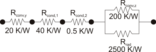
We can understand a lot about the problem by just considering the thermal resistance. For example, since the radiation resistance is in parallel with a much smaller convection resistance, it is going to have a small effect on the overall thermal resistance. Increasing the emissivity of the wall clear to unity would only improve the total thermal resistance by 5%. Or, ignoring radiation completely would cause an error of only 6%. Similarly, the thermal resistance of the steel is in series, and is tiny compared with the other resistances in the system, so no matter what is done to the metal layer it isn’t going to have much effect. Changing from steel to pure copper, for example, would only improve the overall thermal resistance by 0.2%. Finally, it is clear that the controlling thermal resistance is convection on the air side. If it were possible to double the convection coefficient (by, say, increasing the velocity of the air) that step alone would decrease the overall thermal resistance by 36%.

Beyond Plane Wall Conduction

Thermal resistance can also be used for other conduction geometries as long as they can be analyzed as one-dimensional. The thermal resistance to conduction in a cylindrical geometry is:

pic22

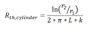
where L is the axial distance along the cylinder, and r1 and r2 are as shown in the figure.

Thermal resistance for a spherical geometry is:

pic23

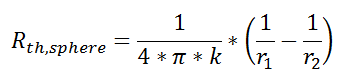
with r1 and r2 as shown in the figure.

pic24

Conclusion

Thermal resistance is a powerful and useful tool for analyzing problems that can be approximated as 1-dimensional, steady-state, and that do not have any sources of heat generation.


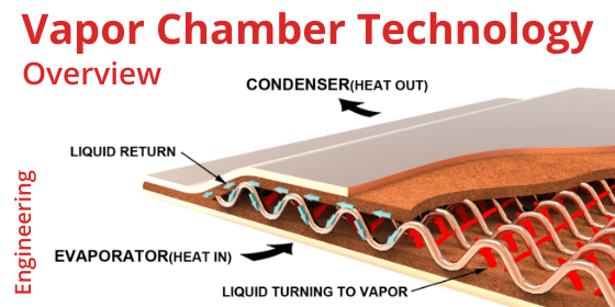
Please contact Celsia with your next thermal design challenge. We specialize in the design and production of heat sinks using liquid two phase devices: heat pipes and vapor chambers.

Related Links

Clean Heat Sink of Dust Bunnies

Clean Heat Sink of Dust Bunnies

Clean Heat Sink of Dust Bunnies


My current notebook is about 18 months old and had been running slower and slower for a few months. It was also noticeably hotter causing the fan to run almost continuously. I knew it was that time. About every year and a half I have to take apart my PC to clean out dust from the fin stack and to replace the thermal grease if I want it to run at peak performance. When I mention this to friends they always look at me strangely. Here’s what I found, and expected to find, when I opened it up.

Fouled Notebook Heatsink

Notebook Heat Sink After 18 Months


Yes, that’s the heat sink. And, for the most part this notebook is used on my desk and most people think I am anal about keeping things neat and tidy. So, this is not from a harsh environment!

And since the processor has been running hot for a few months the grease has started to harden so that needed replacing as well. Whoever put the grease on in the first place used enough for three processors!

Thermal Grease

Thermal Grease


This reminds me of several papers I saw presented some years ago. David Moore of HP showed results in both desktop and laptop systems with failures showing up in less than 1 year1&2. The process begins when hair, and/or thin fibers of fabric or paper begin to layer on top of one another forming an intertwined network. Smaller flakes, usually skin, are then trapped by the matted fibers. Here’s what the process looks like2.

Magnified Dust Bunny

Long Fibers Intertwine then Small Particles Become Trapped


Wanting to understand more about the process he and an HP team created a “Dusty Environment Simulator”, complete with manmade dust – a combination of finely shredded and ground recycled newspaper and attic insulation, with a fire retardant added. The material would be introduced into an enclosed test chamber using a standard flour sifter.

The next step was to test small form-factor desktop systems, each with a different CPU heat sink design. The two I’ll touch on here are a folded fin radial heat sink with a top mount fan and an extruded straight fin heatsink, also with a top mount fan. I pulled these pics off the web for illustrative purposes so show roughly what these sinks look like.

Folded Radial Fin and Extruded Straight Fin Heat Sinks

Folded Radial Fin and Extruded Straight Fin Heat Sinks


His results bowled me over. The radial heat sink had a delta-T which was 3 degrees Celsius better than the extruded fin sink when the systems were tested without dust. However, the radial sink became more quickly clogged with dust causing its delta-T to rise above that of the extruded sink1.

Heat Sink Fouling Test Results

Heat Sink Fouling Test Results


David concluded that while environment is a significant risk factor in heat sink fouling, heat sink design also plays a key role. Here are some of the non-environmental factors that increase vulnerability.

  • Finer pitch heat sinks – provide a shorter distance for fibers to bridge
  • Sheared fin construction – sharp surfaces retain fibers
  • High impingement velocity
  • Close proximity of fan

Hopefully, every one of you is not only reaching for a screwdriver to take apart your own system, but also thinking about these killer dust bunnies when designing your next thermal solution.

Sources

  1. Moore, David A. “The Dust Threat” Presentation to the IMAPS Thermal ATW, October 23rd, 2003
  2. Moore, David A. “Characterization of Fiber Accumulation Fouling in Fine Pitched Heat Sinks” Paper for 25th IEEE Semi-Therm Symposium.

Related Links

Thermal Test Chips

Thermal Test Chips

Thermal Test Chips


To meet aggressive product time-to-market goals, electrical and mechanical engineers need to work concurrently to envision, model and validate an enormous array of interdependent system requirements. While there’s no doubt that robust thermal modeling of both the semiconductor chip and heat sink solution help get ahead of the development curve, there is no substitute for actual test data. But, how do you do that before the final semiconductor chip, along with the associated product costs, is available. Enter the thermal test chip. They can be a convenient, fast and cost effective approach for developing package and cooling solutions at the individual semiconductor and system levels.

What Are Thermal Test Chips?

Thermal test chips are designed to help thermal engineers answer critical thermal packaging or material questions and can be divided into two groups.

  •  Application Specific Test Chips – Designed to mimic complex heat generation topologies such as those found in multi-core processors, system-on-a-chip, and power management and control designs, these thermal test chips are made to match a specific design. They are usually designed by the manufacturer of the corresponding application chip as a tool to help their customers get started on thermal design efforts well before the application chip design and fabrication is done.
  •  General Purpose Test Chips – Like their application specific counterpart, general purpose chips allow engineers to model, measure, and modify silicon design early in the processes. These chips have a standardized design in order to accommodate a wide variety of applications quickly and cost effectively. Yet, customization of the thermal profile and package is still possible.

Let’s take a slightly more in depth look at how one northern California company, Thermal Engineering Associates (TEA), implements these general purpose products.

Goals of General Purpose Thermal Test Chips (TTC)

To be useful to chip designers, TTCs need to meet several requirements including:

  • Chip size that closely approximates the chip being simulated.
  • Maximum possible heating area relative to chip size (JDEC standards specify a minimum of 85%)
  • Uniform temperature profile across the heating area with the ability to simulate hotspots in specific areas.
  • The ability to manipulate and measure different temperature profiles using standard lab equipment.

Design Implementation

TEA uses a ‘Unit Cell’ approach for its general purpose test chips that are manufactured in either flip chip or wire bond versions. Each unit cell is small (1mm or 2.54mm squared) yet can be arrayed into larger shapes up to 20 x 20 unit cells in order to mimic the final application specific chip. As shown below, each unit cell uses metal film resistors for heat flux generation and PN Junction diode(s) for temperature sensing. Power densities of ~300 W/cm2 and ~200 W/cm2 can be achieved for 1mm and 2.54mm unit cells respectively.

1mm Thermal Test Chip

1mm X 1mm Unit Cell (TTC-1001)


2.54mm Thermal Test Chip

2.54mm X 2.54mm Unit Cell (TTC-14002)


Each 2.5mm unit cell has two resistors for heat generation and four diodes for temperature sensing while the 1mm unit cell includes two resistors and one temperature sensor. When configured and tested in an array using a given heat sink, it’s easy to see the precision and versatility of these general purpose test chips.

Arrayed Chips

(L) 2.54mm Unit Cell in 4×4 Array (R) 1mm Unit Cell in 10×10 Array


Even Temp

Uniform Temperature Distribution (L) 4×4 Array (R) 10×10 Array


Hot Spots

Two Hot Spots (L) 4×4 Array (R) 10×10 Array


The use of specialized thermal test chips is a convenient and efficient approach for developing package and cooling solutions. Thermal test chips, as compared to live device measurements, provide measurement accuracy and the ability to simulate high power density areas. Measurement data acquisition is simplified allowing the use of standard lab equipment for powering the resistors and sensing temperatures. No specialized switching equipment is required, reducing the cost for thermal test. The thermal test chip is also suited for advanced development of stacked, 2.5 and 3D packaging and in some cases is the only way temperatures can be detected in a stacked or 3D configuration.


Special thanks to Bernie Siegal of TEA and Tom Tartar of Package Science Services for providing us with information about general purpose thermal test chips. For more information, please visit the TEA website.

Related Links

BTX Form Factor PC | Thermally Superior Design That Failed

BTX Form Factor PC | Thermally Superior Design That Failed

BTX Form Factor PC | Thermally Superior Design That Failed


Not much is written these days about the lowly desktop computer. Smartphones, tablets and laptops take center stage. You may disagree, but I believe the desktop is going to be around for a long time. Its relatively low price and super performance numbers can’t be matched in other form factors. Cloud computing that moves processing power to a remote location and continuing advancements in low power performance chips will further erode desktop sales, especially at the low end, but you’re going to have to pry this design from the dead hands of engineers and scientists who demand high-powered local computing. These types of systems are power pigs and even their lower performing counterparts are getting smaller (small form factor desktops), increasing thermal management challenges.

Why didn’t the market embrace a proposed standard in PC architecture design that offered, among other things, substantially improved thermal headroom? Major OEM’s produced it and millions were sold, yet it remains a virtual footnote in PC system design. I’m talking about BTX architecture (motherboard layout and system design).

Since the mid-1990’s the ATX (Advanced Technology Extended) desktop architecture had been king. Power and power densities of CPUs were still relatively low so this Intel design, later adapted to AMD processors, was never meant to address growing thermal challenges. In those days, Pentium II and III processors were still in the 20-40 watt power range with power densities in the low to high teens (Figure 1).

Figure 1: CPU Power Density (Source: Canturk Isci, Workload Adaptive Power Management)

CPU power densities

As you can see in Figure 2 (excuse my crude airflow drawings), a typical ATX layout positioned the CPU toward the rear of the machine with a single 100mm exhaust fan used to move air through the system. When necessary, a small fan was added on top of the CPU heat sink for further cooling but it distributed warm air throughout the system. Cool inlet air was impeded by forward connectors and memory modules that were perpendicular to, and positioned in front of, the CPU. Graphics cards where designed so that heat sink and associated fan faced toward the bottom of the case. From a thermal management standpoint, this design was marginal but adequate for the time.

Figure 2: Typical ATX Architecture

ATX Design

The long lived Pentium IV, with its’ every increasing power (80-115 watts in later iterations) and power densities (roughly 60-90 w/cm2), forced Intel to rethink ATX architecture and in 2003 it pushed a competing architecture whose primary purpose was better thermal management. The idea was simple. Give the CPU ample cool air and place all component in-line with the air flow.

Figure 3: Sample BTX Architecture

BTX Design

Figure 3 shows the first mass produced BTX design from Gateway (2004). Dell followed with a similar design the next year and HP as well as a few others soon got on board. The CPU was moved to the front of the machine where it could benefit from the coolest air. Rear exhaust fan diameter was generally increased to 120mm and in some cases (shown) at additional 120mm intake fan was added. A shroud was sometimes used to direct intake air over the CPU and move it in a straight line toward the exhaust fan. Additionally memory slots where positioned parallel to air flow and the motherboard was moved to the other side of the case. This allowed graphics cards to be flipped upside-down so the GPU fan received additional air and could more easily direct it toward the exhaust fan. Finally, there existed a thermally efficient desktop system design. Yes it was marginally more expensive – on the order of $10-$15 with larger fans and shrouding in addition to a non-standard layout – but the thermal benefit seemed to outweigh the cost premium.

Engineers are often asked to tackle thermal challenges after system layout is locked. I know it’s not best practice, but it happens more than we’d like to admit. BTX gave us a better platform to manage heat, but it failed despite the fact that the latest generation of desktop processors (Core i7) still has power densities considerably higher than their Pentium III counterparts.

So why did BTX fail to replace an aging ATX design? We’d like to hear your comments.

Please contact us if you’d like to learn more about how Celsia can help with your next heat sink project. We’ve worked on everything from consumer devices to industrial test equipment that require heat sinks to cool anywhere from a few watts to a few kilowatts.

Related Links