This page compares five heat pipe heat sink designs, evaluating their thermal performance and relative cost. It targets horizontally finned configurations where the two-phase device must route through the fins. Each design is analyzed using CFD data, thermal resistance, and cost scaling to guide engineers in selecting the best solution for their needs.
Application Setup and Design Criteria
To ensure a consistent comparison, the following application parameters were used:
-
Heat source power: 250 W
-
Heat source size: 30 × 30 mm
-
Maximum ambient temperature: 25 °C
-
Airflow: 40 CFM
-
Fin block size: 115 × 85 × 65 mm (horizontal fins)
The thermal budget is calculated as the difference between the maximum Tcase and the maximum ambient temperature. This delta must be greater than the heat sink’s temperature rise to ensure proper performance. For example, a 40 °C thermal budget requires the sink to maintain a ΔT below 40 °C. This calculation is important because it drives heat sink choice.
Design 1: Heat Pipe Heat Sink with Aluminum Base
This traditional design uses a solid aluminum base with heat pipes soldered into machined grooves or flattened directly. Thermal grease or a pad is applied between the base and the heat source. Consequently, the heat pipes do not come into direct contact with the heat source.
-
ΔT: 53.9 °C
-
Thermal Resistance: 0.2156 °C/W
-
Relative Cost: 1.0X (baseline)
Although this is the most economical option, its performance is the lowest among the designs evaluated. Given a 25 °C maximum ambient temperature, the thermal budget would need to be above 79 °C (25 + 54).
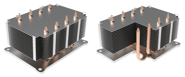
U-Shaped Heat Pipe Heat Sink with Aluminum or Copper (Design 2) Base Plate
Design 2: Heat Pipe Heat Sink with Copper Base
Replacing the aluminum base with copper increases thermal conductivity and improves performance modestly.
-
ΔT: 51.6 °C (a 2.3 °C improvement)
-
Cost Increase: 5% more than aluminum
-
Relative Cost: 1.05X
This option is ideal when a moderate improvement is needed without a significant cost increase. However, for applications where weight is a concern, this option may not be optimal as copper has 3 times the density of aluminum.
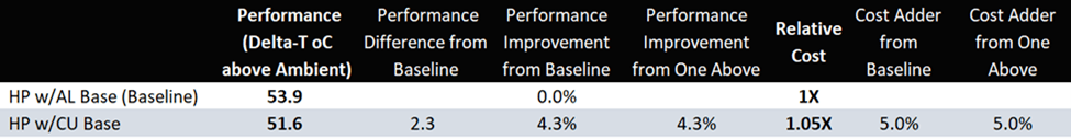
Heat Pipe Heat Sink Cost & Performance of Solid Base Designs
Design 3: Direct Contact Heat Pipe Heat Sink
In this design, the heat source contacts the heat pipes directly. The base plate and solder interface are eliminated, thereby shortening the thermal pathway. However, additional machining is required to flatten the heat pipe surface.
-
ΔT: 49.3 °C
-
Thermal Resistance: 0.1972 °C/W
-
Relative Cost: 1.1X
This configuration offers better performance by removing two thermal junctions, though it incurs a slight cost increase due to machining of the heat pipes for a flatter surface (better heat transfer).
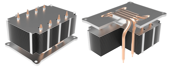
Direct Contact Heat Pipe Heat Sink
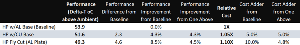
Heat Pipe Heat Sink Cost & Performance of Solid and Direct Contact Heat Pipe Bases
Design 4: U-Shaped Direct Contact Vapor Chamber Heat Sink
This configuration substitutes multiple heat pipes with a single U-shaped vapor chamber. It allows direct contact with the heat source and requires one-piece vapor chamber manufacturing capabilities.
-
ΔT: 37.7 °C (21.5% improvement over direct contact heat pipes)
-
Cost Increase: 4.5%
-
Relative Cost: 1.15X
Although slightly more expensive than Design 3, this approach provides significant performance gains with only a moderate increase in cost and weight.
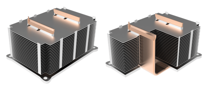
U-Shaped Vapor Chamber
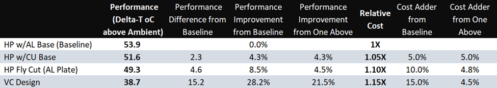
Heat Pipe Heat Sink Cost & Performance of Solid and Direct Contact Bases
Design 5: 3D Vapor Chamber Heat Sink
The most advanced design includes a vapor chamber base with eight brazed condenser tubes aligned vertically. Heat spreads across XY and Z axes, making it well-suited for higher power densities or larger base plates.
-
ΔT: 35.7 °C (best performance)
-
Relative Cost: 2.17X (117% more than Design 4)
Despite its high cost, the 3D vapor chamber delivers unmatched heat spreading, particularly in space-constrained or high-load applications.
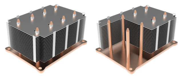
3D Vapor Chamber Heat Sink
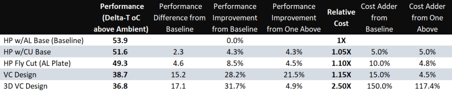
Comparative Table: Heat Pipe Heat Sink Design Cost & Performance of All Options
Summary and Recommendation
From aluminum base to 3D vapor chamber, there’s a 17 °C improvement in thermal performance, albeit at over twice the cost. Moderate gains (2–5 °C) are achieved by switching to copper or direct contact configurations, while vapor chamber solutions provide more substantial improvements.
From a general perspecive, the best choice based on performance and cost is the U-shaped vapor chamber design. However, in practice, the best heat pipe heat sink design depends on the Max Tcase of the heat source. Choose the design whose total temperature rise (max ambient of 25 °C plus the Delta-T from the chart above) is LOWER than the Max Tcase of the heat source.