Summary – This article compares the performance, weight, and cost of three categories of heat sink design: heat sinks with a solid metal base, heat sinks with embedded heat pipe base, and heat sinks with a vapor chamber base. Heat sink fins for all designs are oriented vertically.
For more comparisons see “Heat Pipe Heat Sink Design”, which compares only heat pipe and vapor chamber designs used when the fin stack is oriented horizontally.
Engineers are regularly tasked with heat sink design optimization, making careful trade-offs between heat sink performance, weight, and cost. Sometimes the decision is easy, such as when the low-cost alternative allows the device to meet or exceed all product requirements. However, the decision is more difficult when the thermal budget is tight and/or when a single heat sink is required for different product configurations (higher power semiconductors). In these cases, alternative heat sink designs should be considered.
In this article, we’ll take a look at 5 heat sink design options (in 3 categories), each using a different configuration for the heat sink base:
- Heat Sink Design Category 1: 6mm thick solid metal base (one with aluminum base & one with copper base),
- Heat Sink Design Category 2: embedded heat pipes in a 6mm thick base (copper water heat pipes embedded in both a copper and aluminum base),
- Heat Sink Design Category 3: 4mm thick copper/water vapor chamber base. For all options, the heat source makes direct contact with the device (no mounting plate).

Heat Sink Design Comparison: Solid Metal Base, Embedded Heat Pipe Base, Vapor Chamber Base
Further, each heat sink design is subject to the following operating parameters and performance targets:
- Heat Source: 10x10mm generating 100W
- Tcase Max: 80 oC
- Max Ambient: 45 oC
- Thermal Budget: 35 oC (80-45)
- Target heat sink thermal resistance: 0.35 oC/W or less (35/100)
- TIM: K = 3W/(mK)
- Aluminum Fin Pack Dimensions: 150 x 99 x 30mm.
- Heat Sink Fin Thickness = 0.3mm, Fin Gap = 1.2mm
- Airflow: 50 CFM

Heat Sink Design Category #1: Solid 6mm Metal Base of Either Aluminum or Copper
When evaluating any heat sink design, the single most important parameter is the thermal module delta-T relative to the calculated thermal budget (Tcase Max – Max Ambient). We know max ambient is 45 oC and if we assumed max Tcase was 80 oC, our thermal budget would be 35 oC. As a general rule, consider heat sinks designed with heat pipes or vapor chambers when the thermal budget is below 40 oC. Heat sinks with a lower delta-T will also have reduced thermal resistance.
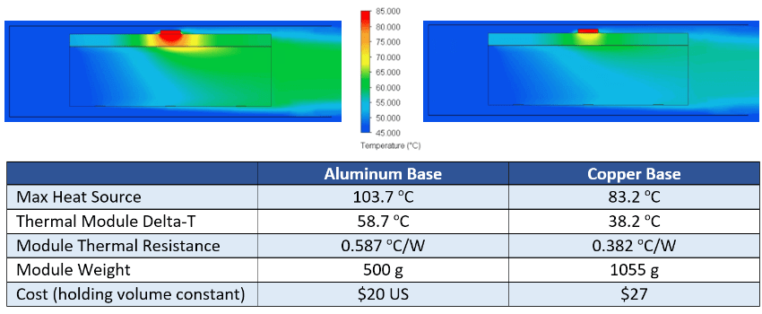
Aluminum Base (L) and Copper Base (R) Heat Sinks
Although the aluminum and copper heat sink designs are the most cost-efficient, neither thermal module delta-T falls within the calculated thermal budget of 35 oC. If the budget was 5 degrees higher, the copper heat sink base version would meet requirements, but at a hefty weight penalty (500 vs 1,055 grams). This could be problematic as many applications have strict shock & vibration and/or portability requirements that dictate heat sink maximum weight. While not shown it the table, increasing the copper base thickness to 12mm yields a thermal module delta-t of 34.4 oC but weighs in at over 1,800 grams.
Heat Sink Design Category #2: Embedded Heat Pipes in Aluminum or Copper Base
In this heat sink design scenario, we’ve added to the heat sink base two 6mm copper/water heat pipes that have been bent and flattened to 3mm. Note that because these are direct contact heat pipes, the surface under the heat source is machined (0.025mm/cm) to ensure good contact between it and the heat source.
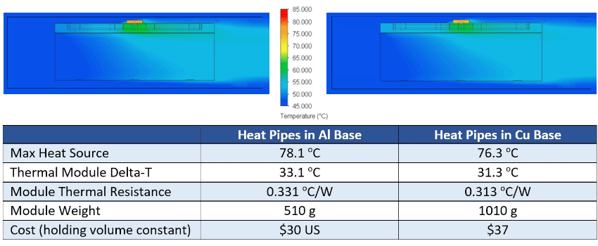
Embedded Heat Pipes in Aluminum Base (L) and Copper Base (R)
Compared with their solid metal base counterparts, adding heat pipes improves heat sink performance (lower delta-t and thermal resistance) by nearly 26 oC for the aluminum version and nearly 8 oC for the copper version. Here we see both heat sinks easily beating our thermal budget of 35 oC. Like our solid metal solutions, weight is roughly doubled for the copper version along with the same numeric increase in price.
Heat Sink Design Category #3: Vapor Chamber (VC) Base
It should come as little surprise that the vapor chamber heat sink design has the lowest thermal resistance, having a delta-T at 26.0 oC – over 5 degrees cooler than the closest alternative. Moreover, the 4mm vapor chamber reduces the overall height of the heat sink by 2mm. If the designer doesn’t need the extra space, it can be added back to the fin area, further decreasing heat sink thermal resistance.
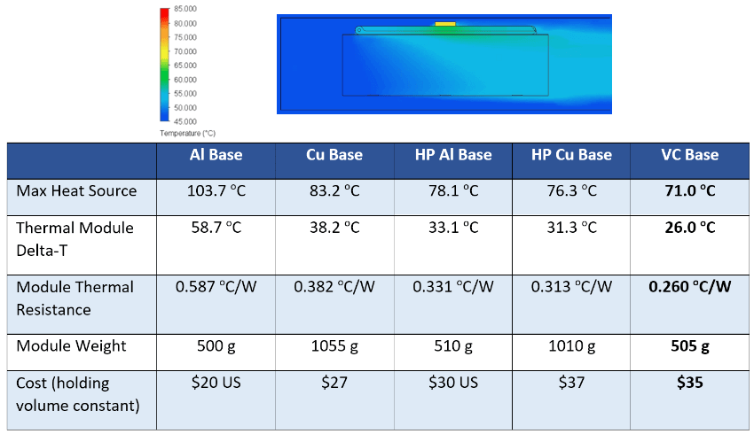
Vapor Chamber Base (far right) Compared with Alternatives
Summing up our choices, we’ve eliminated heat sink designs using a solid metal base as they do not meet thermal requirements but are the least expensive solutions. From a weight and cost perspective, the embedded heat pipe design with an aluminum base is the clear winner unless other factors are taken into account. For instance, if more powerful heat sources are slated for the same form factor and we want to maximize economies of scale for the heat sink (use the same sink across multiple product configurations), then we should calculate maximum power handling capacity without violating our thermal budget.
With a 35 oC thermal budget, we can calculate the following max heat source power input into each of the remaining options.
- Heat Pipe with Aluminum Base: 106 watts (35 oC /0.327 thermal resistance)
- Heat Pipe with Copper Base: 112 watts
- Vapor Chamber Base: 135 watts
Of course, in doing this calculation we need to ensure the two-phase devices themselves can handle the additional power before wick dry-out occurs. In this case, both the heat pipes and the vapor chamber can do so.
Related Links
Celsia is a custom heat sink manufacturer using vapor chamber and heat pipe technology. We specialize in: heat sink design, heat sink proto, heat sink manufacturing, heat pipes, vapor chambers, custom heat pipe wick materials.

