Heat Sink Size Calculator Use Instructions
Heat Sink Size Calculator Use Instructions

How to use the online heat sink size calculator used in the early stages of heat sink design. With the exception of choosing the correct “volumetric thermal resistance”, this is probably our most straight forward calculator.
Here’s the link to the calculator.
Heat Source Power (Q) – This is the thermal design power (TDP) which is the maximum amount of heat, in watts, generated by the chip without exceeding its thermal envelope. It should be provided by the chip manufacturer or ASIC engineer if done in-house.
Tcase Max – the maximum temperature of the chip case. For most chip designs this will be provided by the manufacturer. For bare die chips, the max Tjunction temperature will be given. In this case, use the Tjunction spec in place of Tcase max.
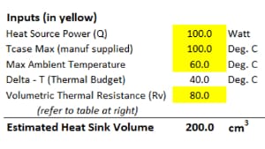
Max Ambient – the maximum ambient temperature at which the device is intended to operate.
Thermal Budget – Tcase Max minus Max Ambient. The sum total of all delta-ts in the network, from Tcase to Air temperature rise cannot exceed this limit.
Note – thermal budgets below 40 degrees Celsius are generally good candidates for two-phase cooling using heat pipes or vapor chambers.
Volumetric Thermal Resistance (Rv) – This equation and subsequent guidelines have been shown to closely estimate heat sink volume: V=(Q*Rv)/Delta T. The first step in using the chart below is to know the available airflow across the heat sink. As you know, the higher the airflow the smaller the heat sink. The first challenge you’ll probably face is that the fan manufacturer has given you the ‘bulk airflow’, usually in cubic feet per minute, but not the air velocity. It’s easy to determine the velocity if you know the size of the heat sink but since we don’t it’s a catch 22. Here are some rough guidelines:
- Open air natural convection develops about 40 LFM which is about just enough to blow out a match.
- 1 m/s or 200 LFM you can feel the flow but not hear it.
- 2.5 m/s or 500 LFM is a good flow that will blow out a whole bunch of candles and you can begin to hear the noise, especially in a quiet environment.
- 5 m/s or 1000 LFM is going to be noisy. Not to be used in any noise-sensitive environment.
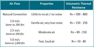
Once you’ve selected the appropriate airflow, the next step is choosing from a range of Rv. In the case of moderate air (2.5 m/s) the range is 80-150. The published rule is as follows:
- For heat sinks smaller than 300 cm3 you use the lower limit, in this case 80.
- For large heat sinks, greater than 1,000 cm3 use the upper limit.
However, like the CFM to LFM calculation we have a bit of a chicken and egg scenario. My suggestion – use something in the middle to gauge the rough size of the heat sink and adjust from there. For example, if you initially use 115 Rv value and the estimated volume of the heat sink is less than 300 cm3, change the Rv to 80, which is the lower end of the Rv value for moderate airflow.
When designing devices that must work at altitude, it’s important to de-rate the Rv. A solid rule of thumb is 10% for every mile of altitude. For example, at one mile high we’d divide 80 Rv by 0.9 to end up with a de-rated Rv of roughly 89.
Once you’ve determined the volume of the heat sink, the last step is to assign some length, width and height dimensions. Initially, this is generally driven by space constraints so enter some figures and see if you come close to matching the required volume. One note here, we have an online heat sink performance calculator that you might play with to more finely tune heat sink base and fin height.
Related Links