Heat Sink Design Fundamentals
When designing or choosing a heat sink, thermal engineers try to optimize sometimes competing performance requirements with cost priorities. In addition to maintaining optimal electronics component temperatures, the final heat sink design must also meet size, weight, durability, and cost requirements. This page is organized to help engineers structure their thinking around the numerous variables considered when choosing or designing an air-cooled, non-pumped liquid heat sinking. Topics include:
- Basics of Heat Transfer, Thermal Resistance, & Initial Calculations
- Heat Sink Material Selection
- Aluminum
- Copper
- Heat Pipes / Vapor Chambers
- Heat Sink Fin Geometry
- Fin Shape
- Fin Spacing
- Fin Height
- Heat Sink Manufacturing & Cost Considerations
Basics of Heat Transfer, Thermal Resistance, & Initial Heat Sink Calculations
Heat transfer occurs through conduction, convection, and radiation. Understanding the definition and relative importance each has on heat sink design helps engineers identify heat sink problem areas to keep the total temperature rise (Delta-T) of the thermal solution below the calculated thermal budget.
Heat Transfer Concepts
Conduction – transfer of heat through a solid material due to the vibration and movement of atoms and molecules. In a heat sink, conduction occurs as heat moves from the electronic component through the thermal interface material(s), the heat sink’s base, and the fins. In a heat sink application, conduction is critical for transferring heat from the heat source (e.g., electronic component) to the heat sink. It is crucial to ensure that heat is effectively spread throughout the heat sink before being dissipated to the surrounding environment.
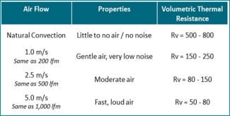
Convection – transfer of heat between a solid surface and a fluid (such as air or liquid) in motion. Heat sinks primarily rely on convection to dissipate heat into the surrounding environment. Convective heat transfer can be either natural (passive) or forced (active). For heat sink applications, convection is the tail that wags the dog in the sense that it’s the primary exit point for heat yet determines how big the heat sink needs to be. The efficiency of convective heat transfer depends on factors such as airflow, the surface area of the fins, and fin geometry.
Radiation – heat transfer through electromagnetic waves, typically in the infrared spectrum. Its contribution to heat transfer in heat sinks is generally much smaller compared to conduction and convection. Radiation becomes more important at higher temperatures, as the rate of heat transfer through radiation increases with the fourth power of the absolute temperature. However, in most electronic cooling applications, the operating temperatures are not high enough for radiation to have a significant impact on the overall heat transfer.
The portion of total heat sink thermal resistance caused by conduction is usually higher for applications directing airflow across the fin stack as fans or blowers aid in heat transfer away from the sinks and into the surrounding air. Conversely, those applications using natural convection generally have the bulk of their thermal resistance caused by convection.
Thermal Resistance Drives Delta-T
Heat sink thermal performance is determined by adding each of the thermal resistances in the network and then multiplying that number (in oC/w) by the maximum power output of the heat source (TDP in watts) to get the total heat sink temperature rise.
The components of the thermal resistance network are shown on the right in the illustration below while the heat transfer mechanism associated with those resistances are shown on the left.
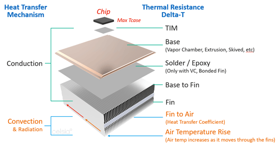
Heat Sink Thermal Resistance Diagram
In a heat sink, there are layers of thermal resistance that affect the overall thermal performance. These include: the TIMs, bse of the heat sink, surface area of the fins, and available airflow across the fins. The thermal resistance for each of these components can be described as follows: Lower numbers indicate better performance.
- (R_TIM): This thermal resistance represents the heat transfer between the component’s case (Tcase) and the heat sink base. The efficiency of this heat transfer depends on the material conductivity and thickness of the thermal interface material (TIM) applied between the case and the base, as well as the contact area and pressure.
- Base to fin (R-base-fin): This thermal resistance applies where fins are attached to a base and represents the heat transfer from the heat sink base to the fins. The efficiency of this heat transfer is influenced by the material used to join the fins to the base. Solder is the preferred method and results in a low-resistance. Epoxies can be used for larger assemblies where soldering is impractical or not required. This is typically a small number but needs to be part of the calculation.
- Fin to air (R-fin-air): This thermal resistance represents the heat transfer between the fin surface area and the surrounding air. This heat transfer occurs primarily through convection, and its efficiency depends on the velocity of the air flow which affects the rate of heat flow (heat transfer coefficient)
- Air Temperature Rise (R_-air-rise ): In a cooling system, the heat generated by electronic components is transferred to the heat sink, which then dissipates the heat to the surrounding air. This causes an increase in the temperature of the air as the air flows through the heat sink in effect increasing the “ambient temperature” along the heat sink length. This is directly affected by the bulk air flow going through the heat sink.
The overall thermal resistance of the heat sink (R_total) can be estimated by adding the individual thermal resistance layers:
R_total = R-TIM + R-base conduction+R_base-fin + R_fin-air + R_air-rise
Engineers aim to minimize the total heat sink thermal resistance to ensure efficient heat dissipation and maintain the optimal operating temperature for the heat-generating components. By understanding the individual temperature rises at each stage of the thermal resistance chain, engineers can identify problem areas and quickly move toward relevant solutions. Visit our online heat sink performance calculator to show these values for a specific application.
Initial Calculations Used in Heat Sink Design
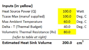
The first two calculations likely to influence heat sink design requirements are thermal budget and maximum heat sink thermal resistance. Fortunately, they are easy to calculate from readily available information about the environment(s) in which the end product is designed to operate and about the heat source(s) used in that product.
- Thermal Budget – Expressed in degrees of temperature rise, this figure sets the upper limit for the maximum temperature rise, Delta-T, of the thermal solution. It is calculated as follows:
Heat Sink Thermal Budget = Max Ambient Operating Temperature – Max Tcase Temperature
Example: Tamb-max = 55 Tcase max =85 30°C thermal budget
- Required Heat Sink Theta (Rth) – Expressed in degrees of temperature rise per watt of heat source power (°C/w), this figure sets the upper thermal resistance limit for the heat sink solution. It’s calculated as follows:
Heat Sink Theta = Thermal Budget / IC Thermal Design Power
30°C/100w = 0.3°C/w
If it’s an off-the-shelf IC, the datasheet provides both the Max T-case for lidded ICs. In the case of unlidded ICs, the datasheet will provide Max T-Junction from which the thermal resistance of the heat spreader and TIM will need to be added to the total thermal resistance network (delta-t calculation).
Heat Sink Design Material Considerations
Material selection plays a vital role in heat sink design, as it directly affects both the thermal performance of the heat sink and the compatibility of mating surfaces (coatings/plating).
Heat sink thermal resistance and thermal conductivity are related concepts that describe different aspects of a heat sink’s performance in dissipating heat. Here’s how they are connected:
Thermal resistance: Thermal resistance is a measure of a heat sink’s ability to dissipate heat from a heat-generating component to the surrounding environment. It is typically expressed in units of degrees Celsius per watt (°C/W). A lower thermal resistance indicates more effective heat dissipation.
Thermal conductivity: Thermal conductivity is a property of a material that quantifies its ability to conduct heat. It is typically expressed in units of watts per meter-kelvin (W/m·K). Materials with high thermal conductivity, such as copper and aluminum, are good at transferring heat and are commonly used in heat sink designs. The thermal conductivity of solid metals is constant, while heat pipe thermal conductivity varies depending on several factors.
The relationship between heat sink thermal resistance and thermal conductivity is that the thermal conductivity of the material used in a heat sink directly impacts the heat sink’s thermal resistance. A heat sink made from a material with high thermal conductivity will generally have lower thermal resistance and provide better heat dissipation compared to one made from a material with lower thermal conductivity.
The table below lists the thermal conductivities of commonly used metals, two-phase devices, and TIMs used in heat sinks.
| Material | Type | Thermal Conductivity (W/m·K) |
| Aluminum | Metal | 205-230 |
| Copper | Metal | 386-401 |
| Heat Pipe / Vapor Chamber | Two-Phase | 2,000-25,000 (typical for electronics cooling) |
| Thermal grease/paste | Thermal Interface | 0.5-6 |
| Thermal pads | Thermal Interface | 1-10 |
| Graphite | Thermal Interface | 200-500 |
| Phase change materials | Thermal Interface | 0.5-4 |
| Thermal adhesive | Thermal Interface | 0.5-3 |
Aluminum Heat Sinks
Aluminum is the most widely used heat sink material for a variety of reasons:
- Thermal conductivity: Aluminum has a relatively high thermal conductivity (about 205 W/mK), which means it can efficiently transfer heat from a heat source to a cooler area. While other materials, like copper, have higher thermal conductivity, aluminum still provides good performance at a lower cost.
- Lightweight: Aluminum has a low density (about 2.7 g/cm³) compared to other metals, making it lightweight. This is particularly important in applications where weight is a concern, such as in mobile devices, laptops, or aerospace applications.
- Cost-effectiveness: Aluminum is abundant in the Earth’s crust, making it relatively inexpensive to produce and process. It is more cost-effective than other materials with similar thermal conductivity properties, such as copper or silver.
- Ease of fabrication: Aluminum is a soft and ductile material, which makes it easy to cut, shape, and machine. This allows for the production of complex heat sink designs that can maximize surface area and optimize heat dissipation.
- Corrosion resistance: Aluminum forms a thin layer of aluminum oxide on its surface when exposed to air, which protects it from further corrosion. This property makes aluminum heat sinks durable and reliable in various environments.
- Anodizing capability: Aluminum can be anodized to increase its surface hardness, wear resistance, and thermal emissivity (heat transfer due to radiation). Anodizing also allows for the addition of color to heat sinks, which can be aesthetically pleasing or help with branding.
When thermal resistance due to conduction is pushing the thermal solution over the thermal budget, engineers often turn to copper to help solve this issue.
Copper Heat Sinks
To improve thermal performance through lower thermal resistance, engineers sometimes use copper in the base or base and fin sections of the heat sink. With a thermal conductivity of around 400 W/mK, copper can half the delta-t of thermal resistance due to conduction, but some notable disadvantages.
- Cost & Weight: Copper is roughly 3 to 4 times as expensive per pound as aluminum, but with a density (8.96 g/cm³) three times that of aluminum its final cost is 9 to 12 times that of the same size aluminum alternative. Even when cost is not prioritized, the weight penalty of this material forces engineers in portable electronics, aerospace, and automotive to consider other options.
- Machinability: Copper is less machinable than aluminum, making it more difficult to cut, shape, and form into complex heat sink designs. This can result in increased production time and higher manufacturing costs.
- Corrosion resistance: While copper has decent corrosion resistance, it is not as corrosion-resistant as aluminum. Aluminum forms a stable and protective oxide layer when exposed to air, providing better corrosion resistance than the oxide layer formed on copper.
- Anodizing capability: Aluminum can be anodized to improve its surface properties, such as hardness, wear resistance, and thermal emissivity. Anodizing also allows for color customization. Copper, on the other hand, cannot be anodized, limiting its surface treatment options compared to aluminum.
When both performance and weight or critical design features, engineers may incorporate heat pipes or vapor chambers into their heat sink designs.
Heat Pipe Heat Sinks
Heat sink designs using heat pipes or vapor chambers can substantially decrease thermal resistance due to conduction, allowing engineers to reach lower thermal budget targets. The reason for the improvement is the higher thermal conductivity of two-phase devices. However, this figure which generally ranges between 2k-25k W/mK for electronics cooling applications is highly dependent on the distance heat travels to reach the fin section of the thermal solution; the longer the distance, the higher the thermal conductivity.
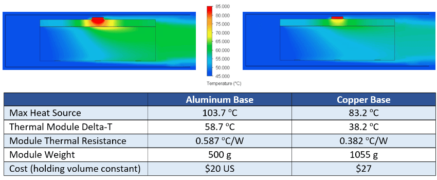
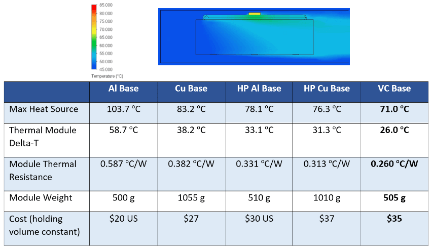
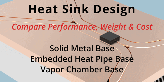
Using CFD software, Celsia modeled five competing heat sink designs where conduction thermal resistance was critical: solid aluminum base, solid copper base, aluminum base with embedded heat pipes, copper base with embedded heat pipes, and a vapor chamber base.

Heat Sink Performance Comparison
As seen in the table above, simply adding heat pipes to an aluminum base decreased thermal resistance by almost 50%, reducing the delta-t in the heat sinks base from 57.8 °C to to 33.2 °C with only a 2% increase in weight. However, there was a 50% cost increase but this is often necessary when thermal performance becomes more important.
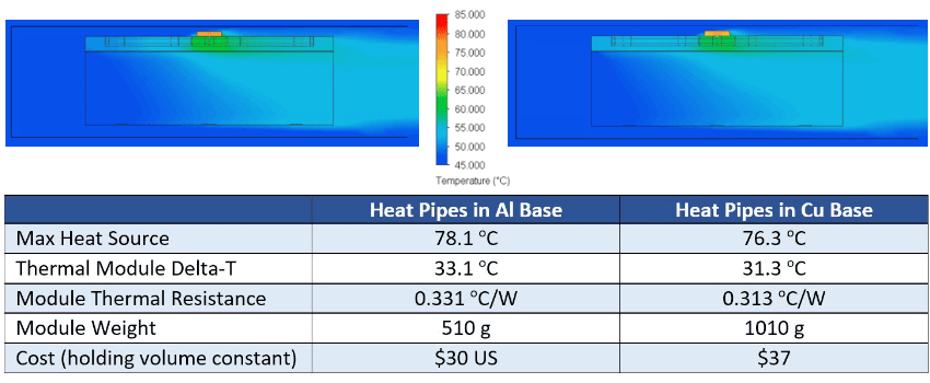
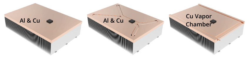
In a second CFD analysis, five different kinds of heat pipe heat sinks were modeled. Here, the challenge was getting the heat a fin stack with fins parallel to the heat source.
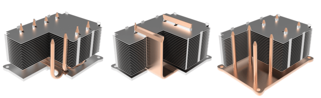
Different Heat Pipe Heat Sink Configurations
This design exercise demonstrates how versatile different types of heat pipe designs can be at reducing the overall solution delta-t. For instance, the heat sink version using an all-aluminum base with attached U-shaped heat pipes had a delta-T of 53.9 °C compared to 37.8 °C delta-T for a U-shaped vapor chamber configuration making direct contact with the heat source.
Heat Sink Design Fin Geometry
Proper heat sink fin geometry is crucial for achieving efficient heat sink designs. Factors such as airflow, pressure drop, material properties, structural integrity, environmental exposure, and manufacturing methods all contribute to determining the ideal fin shape, thickness, spacing, and height for a given heat sink application.
Fin Shape
Broadly speaking, heat sink fin shape falls into two categories: plate fins and pin fins. Plate fins are flat, parallel fin structures that extend from a heat sink base, providing a large surface area for heat transfer. Pin fins are cylindrical or elongated protrusions that extend from a heat sink base, offering improved air circulation.
In forced convection situations with high, directional airflow, plate fins often provide better performance due to their larger surface area and more streamlined shape. However, pin fins can offer superior performance in situations with multidirectional airflow as they allow for better air circulation around the fins.
The available space and weight limitations in the application can also influence the choice between plate fins and pin fins. Plate fin heat sinks tend to have a more compact profile, which may be advantageous in space-constrained applications. Pin fin heat sinks can offer better performance per unit volume in lower airflows and can be more easily adapted to irregular shapes.
Further, pin fins may be preferable in environments with dust or debris as they are less prone to clogging and easier to clean compared to plate fins.
Sub-categories of plate fins and pin fins include:
Plate Fins:
- Straight Fins: These are the most common type of plate fins, featuring straight, parallel fins extending perpendicularly from the base of the heat sink.
- Louvered Fins: Louvered fins have small, angled slits or cuts along their air flow path, which can enhance heat transfer by promoting turbulence and increasing the effective heat transfer coefficient.
- Wavy Fins: Wavy fins have a sinusoidal or zigzag shape, which can create more turbulence and improve heat transfer, particularly in natural convection scenarios.
- Offset Strip Fins: These fins feature small, staggered plates that are attached to the base of the heat sink in an alternating fashion. This arrangement can promote turbulence and improve heat transfer, particularly in forced convection scenarios.
Pin Fins:
- Cylindrical Pin Fins: These are the most common type of pin fins, featuring cylindrical pins extending perpendicularly from the base of the heat sink.
- Conical Pin Fins: Conical pin fins have a tapered shape, which can reduce airflow resistance and pressure drop, particularly in forced convection scenarios.
- Elliptical Pin Fins: Elliptical pin fins have an elliptical or oval-shaped cross-section, which can improve heat transfer by promoting better mixing of the fluid around the pins and lower pressure drop
The choice of subcategories for plate fins and pin fins depends on various factors, such as the required heat transfer performance, the type of convection (natural or forced), and the specific application requirements along with tooling and production costs.
Fin Thickness
The thickness of fins in a heat sink is a complex consideration influenced by multiple factors. One significant aspect is the thermal conductivity of the material used in the heat sink. Higher thermal conductivity materials, like copper, enable better heat transfer along the fins, allowing for thinner fins or lower fin delta-Ts. In contrast, lower conductivity materials, usually aluminum, require thicker fins, but it also offers lower-cost manufacturing methods.
Apart from thermal conductivity, fin thickness also impacts the structural stability of the heat sink. Thicker fins offer better mechanical strength and can withstand deformation or damage better than thinner fins. However, thicker fins can increase the overall weight and size of the heat sink, which may be undesirable for certain applications.
Fin Spacing
The spacing between fins, also known as the fin gap, is a crucial key factor in determining the heat transfer efficiency of a heat sink. Proper spacing is essential for allowing adequate airflow with either natural or forced convection between the fins, which is essential for efficient heat dissipation. When fins are too closely spaced, airflow becomes impeded, and the increased pressure drop leads to reduced air flow and heat transfer efficiency. On the other hand, fins that are too widely spaced are inefficient and suboptimal. In addition to this, fin spacing affects the accumulation of dust and other particulates that can impede airflow and degrade the heat sink’s performance over time. Increasing the fin spacing can help reduce the accumulation of dust and other particles and facilitate easier cleaning, thereby improving the heat sink’s performance and reliability.
Fin Height
Fin height is another key factor in determining the heat transfer efficiency of a heat sink. Increasing the height of the fins can provide additional surface area, potentially leading to improved performance. However, taller fins may also add weight and cost to the heat sink, which can impact its overall effectiveness. In practice, taller fins can offer a larger face area for air to flow through, resulting in lower pressure drops and enhanced heat transfer performance. Therefore, the optimal fin height depends on the specific application requirements, operating conditions, and the trade-off between performance, weight, and cost. Ultimately, proper consideration of fin height can help optimize heat sink performance, but it should be balanced with other design factors, such as fin spacing and airflow velocity, to achieve the best results.
Unlike heat sink materials that can are chosen for a variety of reasons – optimize performance, weight, durability, etc, fin geometry is primarily determined by performance criteria. Thin or closely spaced, or very tall fins cannot be used in natural convection applications. While engineers may be able to tweak these variables, they should do so only in small amounts. However, the cost component can be optimized, once the design is set, by choosing the manufacturing process that best matches performance, volume, and fin type goals. To see the effect of changes to fin geometry, visit our online heat sink performance calculator.
Heat Sink Types, Manufacturing Method & Cost Considerations
While types of heat sinks can be broken down into categories based on the amount of airflow and type of material, the manufacturing method used to produce the product affects cost. Each manufacturing technique has its advantages and limitations, and not all techniques are suitable for both straight fins (plate fins) and pin fins. Here is a summary of the mentioned manufacturing techniques and their suitability for straight fins and pin fins.
Extrusion: Suitable for Straight Fins but can Approximate Pin Fin
Extrusion is a common manufacturing technique for straight fins, where a metal (typically aluminum) is forced through a die with the desired fin shape. This method is cost-effective and can produce large, continuous lengths of heat sinks with uniform cross-sections. Aiming to emulate heat pin fin heat sinks produced by forging, extrusion manufacturers can cross-cut plate fin heat sinks.
Forged: Suitable for Pin Fin or Straight Fin
Forging is a manufacturing process that employs high pressure and heat to transform a solid metal piece, such as aluminum or copper, into the desired shape for heat sinks. The forged heat sinks boast improved grain structure and orientation, resulting in enhanced thermal conductivity and mechanical properties. Although forging allows for the creation of complex geometries and intricate designs, it may have some limitations in design flexibility. Nevertheless, forged heat sinks offer a reliable and efficient solution for various thermal management applications, particularly when high strength, durability, and heat dissipation are crucial requirements.
Stamping: Suitable for Straight Fins
Stamping is a process where metal sheets are cut and formed into the desired fin shapes using a stamping press. This method is typically used for straight fins made from thin metal sheets, such as aluminum or copper. Stamping is not suitable for pin fins due to their complex geometries and the limitations of the stamping process.
Skiving: Suitable for Straight Fins
Skiving is a manufacturing technique that involves cutting and forming thin layers of metal from a solid block using a specialized tool. This process can produce straight fins with high aspect ratios and tight tolerances. Skiving is generally not suitable for pin fins due to the unique geometry and arrangement of the pins.
Bonded: Suitable for Straight Fins
Bonded fins are created by attaching individual fins, either straight or pin, to a heat sink base using adhesives, brazing, or soldering. This technique allows for more complex fin arrangements and can be used for both straight and pin fins. However, bonded fins may have lower thermal performance compared to other manufacturing methods due to the added thermal resistance at the fin-base interface.
Zipper Fins: Suitable for Straight Fins
Zipper fins are a type of straight fin heat sink created by folding a thin metal sheet, typically aluminum or copper, into a continuous, interlocking fin structure. This method allows for high-density fin arrangements and is particularly suitable for forced convection applications. Zipper fins are not suitable for pin fins due to the nature of the folding process and the unique geometries of pin fins.
In conclusion, selecting the appropriate heat sink is a vital task for thermal engineers to ensure the optimal performance of electronic components while balancing size, weight, durability, and cost requirements. By understanding the essential aspects of heat transfer, thermal resistance, material selection, fin geometry and heat sink manufacturing methods engineers can make informed decisions when designing or choosing a heat sink to meet the specific needs of their application.

 Heat Sink Airflow Direction