When designing or choosing a heat sink, thermal engineers try to optimize sometimes competing performance requirements with cost priorities. In addition to maintaining optimal electronics component temperatures, the final heat sink design must also meet size, weight, durability, and cost requirements. This page is organized to help engineers structure their thinking around the numerous variables considered when choosing or designing an air-cooled, non-pumped liquid heat sinking. Topics include:
Basics of Heat Transfer, Thermal Resistance, & Initial Calculations
Heat transfer occurs through conduction, convection, and radiation. Understanding the definition and relative importance each has on heat sink design helps engineers identify heat sink problem areas to keep the total temperature rise (Delta-T) of the thermal solution below the calculated thermal budget.
Heat Transfer Concepts
Conduction – transfer of heat through a solid material due to the vibration and movement of atoms and molecules. In a heat sink, conduction occurs as heat moves from the electronic component through the thermal interface material(s), the heat sink’s base, and the fins. In a heat sink application, conduction is critical for transferring heat from the heat source (e.g., electronic component) to the heat sink. It is crucial to ensure that heat is effectively spread throughout the heat sink before being dissipated to the surrounding environment.
Convection – transfer of heat between a solid surface and a fluid (such as air or liquid) in motion. Heat sinks primarily rely on convection to dissipate heat into the surrounding environment. Convective heat transfer can be either natural (passive) or forced (active). For heat sink applications, convection is the tail that wags the dog in the sense that it’s the primary exit point for heat yet determines how big the heat sink needs to be. The efficiency of convective heat transfer depends on factors such as airflow, the surface area of the fins, and fin geometry.
Radiation – heat transfer through electromagnetic waves, typically in the infrared spectrum. Its contribution to heat transfer in heat sinks is generally much smaller compared to conduction and convection. Radiation becomes more important at higher temperatures, as the rate of heat transfer through radiation increases with the fourth power of the absolute temperature. However, in most electronic cooling applications, the operating temperatures are not high enough for radiation to have a significant impact on the overall heat transfer.
The portion of total heat sink thermal resistance caused by conduction is usually higher for applications directing airflow across the fin stack as fans or blowers aid in heat transfer away from the sinks and into the surrounding air. Conversely, those applications using natural convection generally have the bulk of their thermal resistance caused by convection.
Thermal Resistance Drives Delta-T
Heat sink thermal performance is determined by adding each of the thermal resistances in the network and then multiplying that number (in oC/w) by the maximum power output of the heat source (TDP in watts) to get the total heat sink temperature rise.
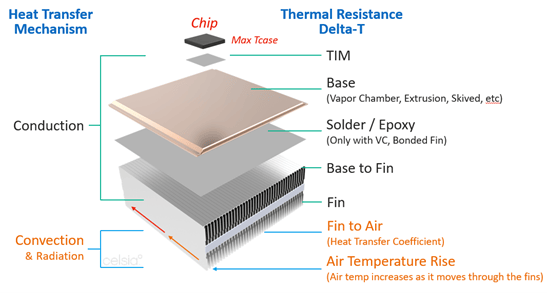
The components of the thermal resistance network are shown on the right in the illustration below while the heat transfer mechanism associated with those resistances are shown on the left.
Heat Sink Thermal Resistance Diagram
In a heat sink, there are layers of thermal resistance that affect the overall thermal performance. These include: the TIMs, bse of the heat sink, surface area of the fins, and available airflow across the fins. The thermal resistance for each of these components can be described as follows: Lower numbers indicate better performance.
(R_TIM): This thermal resistance represents the heat transfer between the component’s case (Tcase) and the heat sink base. The efficiency of this heat transfer depends on the material conductivity and thickness of the thermal interface material (TIM) applied between the case and the base, as well as the contact area and pressure.
Base to fin (R-base-fin): This thermal resistance applies where fins are attached to a base and represents the heat transfer from the heat sink base to the fins. The efficiency of this heat transfer is influenced by the material used to join the fins to the base. Solder is the preferred method and results in a low-resistance. Epoxies can be used for larger assemblies where soldering is impractical or not required. This is typically a small number but needs to be part of the calculation.
Fin to air (R-fin-air): This thermal resistance represents the heat transfer between the fin surface area and the surrounding air. This heat transfer occurs primarily through convection, and its efficiency depends on the velocity of the air flow which affects the rate of heat flow (heat transfer coefficient)
Air Temperature Rise (R_-air-rise ): In a cooling system, the heat generated by electronic components is transferred to the heat sink, which then dissipates the heat to the surrounding air. This causes an increase in the temperature of the air as the air flows through the heat sink in effect increasing the “ambient temperature” along the heat sink length. This is directly affected by the bulk air flow going through the heat sink.
The overall thermal resistance of the heat sink (R_total) can be estimated by adding the individual thermal resistance layers:
Engineers aim to minimize the total heat sink thermal resistance to ensure efficient heat dissipation and maintain the optimal operating temperature for the heat-generating components. By understanding the individual temperature rises at each stage of the thermal resistance chain, engineers can identify problem areas and quickly move toward relevant solutions. Visit our online heat sink performance calculator to show these values for a specific application.
Initial Calculations Used in Heat Sink Design
The first two calculations likely to influence heat sink design requirements are thermal budget and maximum heat sink thermal resistance. Fortunately, they are easy to calculate from readily available information about the environment(s) in which the end product is designed to operate and about the heat source(s) used in that product.
Thermal Budget – Expressed in degrees of temperature rise, this figure sets the upper limit for the maximum temperature rise, Delta-T, of the thermal solution. It is calculated as follows:
Heat Sink Thermal Budget = Max Ambient Operating Temperature – Max Tcase Temperature
Example: Tamb-max = 55 Tcase max =85 30°C thermal budget
Required Heat Sink Theta (Rth) – Expressed in degrees of temperature rise per watt of heat source power (°C/w), this figure sets the upper thermal resistance limit for the heat sink solution. It’s calculated as follows:
Heat Sink Theta = Thermal Budget / IC Thermal Design Power
30°C/100w = 0.3°C/w
If it’s an off-the-shelf IC, the datasheet provides both the Max T-case for lidded ICs. In the case of unlidded ICs, the datasheet will provide Max T-Junction from which the thermal resistance of the heat spreader and TIM will need to be added to the total thermal resistance network (delta-t calculation).
Heat Sink Design Material Considerations
Material selection plays a vital role in heat sink design, as it directly affects both the thermal performance of the heat sink and the compatibility of mating surfaces (coatings/plating).
Heat sink thermal resistance and thermal conductivity are related concepts that describe different aspects of a heat sink’s performance in dissipating heat. Here’s how they are connected:
Thermal resistance: Thermal resistance is a measure of a heat sink’s ability to dissipate heat from a heat-generating component to the surrounding environment. It is typically expressed in units of degrees Celsius per watt (°C/W). A lower thermal resistance indicates more effective heat dissipation.
Thermal conductivity: Thermal conductivity is a property of a material that quantifies its ability to conduct heat. It is typically expressed in units of watts per meter-kelvin (W/m·K). Materials with high thermal conductivity, such as copper and aluminum, are good at transferring heat and are commonly used in heat sink designs. The thermal conductivity of solid metals is constant, while heat pipe thermal conductivity varies depending on several factors.
The relationship between heat sink thermal resistance and thermal conductivity is that the thermal conductivity of the material used in a heat sink directly impacts the heat sink’s thermal resistance. A heat sink made from a material with high thermal conductivity will generally have lower thermal resistance and provide better heat dissipation compared to one made from a material with lower thermal conductivity.
The table below lists the thermal conductivities of commonly used metals, two-phase devices, and TIMs used in heat sinks.
Material
Type
Thermal Conductivity (W/m·K)
Aluminum
Metal
205-230
Copper
Metal
386-401
Heat Pipe / Vapor Chamber
Two-Phase
2,000-25,000 (typical for electronics cooling)
Thermal grease/paste
Thermal Interface
0.5-6
Thermal pads
Thermal Interface
1-10
Graphite
Thermal Interface
200-500
Phase change materials
Thermal Interface
0.5-4
Thermal adhesive
Thermal Interface
0.5-3
Aluminum Heat Sinks
Aluminum is the most widely used heat sink material for a variety of reasons:
Thermal conductivity: Aluminum has a relatively high thermal conductivity (about 205 W/mK), which means it can efficiently transfer heat from a heat source to a cooler area. While other materials, like copper, have higher thermal conductivity, aluminum still provides good performance at a lower cost.
Lightweight: Aluminum has a low density (about 2.7 g/cm³) compared to other metals, making it lightweight. This is particularly important in applications where weight is a concern, such as in mobile devices, laptops, or aerospace applications.
Cost-effectiveness: Aluminum is abundant in the Earth’s crust, making it relatively inexpensive to produce and process. It is more cost-effective than other materials with similar thermal conductivity properties, such as copper or silver.
Ease of fabrication: Aluminum is a soft and ductile material, which makes it easy to cut, shape, and machine. This allows for the production of complex heat sink designs that can maximize surface area and optimize heat dissipation.
Corrosion resistance: Aluminum forms a thin layer of aluminum oxide on its surface when exposed to air, which protects it from further corrosion. This property makes aluminum heat sinks durable and reliable in various environments.
Anodizing capability: Aluminum can be anodized to increase its surface hardness, wear resistance, and thermal emissivity (heat transfer due to radiation). Anodizing also allows for the addition of color to heat sinks, which can be aesthetically pleasing or help with branding.
When thermal resistance due to conduction is pushing the thermal solution over the thermal budget, engineers often turn to copper to help solve this issue.
Copper Heat Sinks
To improve thermal performance through lower thermal resistance, engineers sometimes use copper in the base or base and fin sections of the heat sink. With a thermal conductivity of around 400 W/mK, copper can half the delta-t of thermal resistance due to conduction, but some notable disadvantages.
Cost & Weight: Copper is roughly 3 to 4 times as expensive per pound as aluminum, but with a density (8.96 g/cm³) three times that of aluminum its final cost is 9 to 12 times that of the same size aluminum alternative. Even when cost is not prioritized, the weight penalty of this material forces engineers in portable electronics, aerospace, and automotive to consider other options.
Machinability: Copper is less machinable than aluminum, making it more difficult to cut, shape, and form into complex heat sink designs. This can result in increased production time and higher manufacturing costs.
Corrosion resistance: While copper has decent corrosion resistance, it is not as corrosion-resistant as aluminum. Aluminum forms a stable and protective oxide layer when exposed to air, providing better corrosion resistance than the oxide layer formed on copper.
Anodizing capability: Aluminum can be anodized to improve its surface properties, such as hardness, wear resistance, and thermal emissivity. Anodizing also allows for color customization. Copper, on the other hand, cannot be anodized, limiting its surface treatment options compared to aluminum.
When both performance and weight or critical design features, engineers may incorporate heat pipes or vapor chambers into their heat sink designs.
Heat Pipe Heat Sinks
Heat sink designs using heat pipes or vapor chambers can substantially decrease thermal resistance due to conduction, allowing engineers to reach lower thermal budget targets. The reason for the improvement is the higher thermal conductivity of two-phase devices. However, this figure which generally ranges between 2k-25k W/mK for electronics cooling applications is highly dependent on the distance heat travels to reach the fin section of the thermal solution; the longer the distance, the higher the thermal conductivity.
Using CFD software, Celsia modeled five competing heat sink designs where conduction thermal resistance was critical: solid aluminum base, solid copper base, aluminum base with embedded heat pipes, copper base with embedded heat pipes, and a vapor chamber base.
Heat Sink Performance Comparison
As seen in the table above, simply adding heat pipes to an aluminum base decreased thermal resistance by almost 50%, reducing the delta-t in the heat sinks base from 57.8 °C to to 33.2 °C with only a 2% increase in weight. However, there was a 50% cost increase but this is often necessary when thermal performance becomes more important.
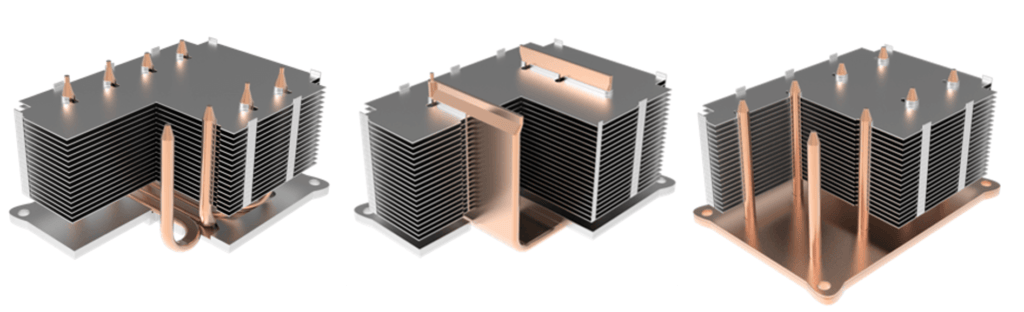
In a second CFD analysis, five different kinds of heat pipe heat sinks were modeled. Here, the challenge was getting the heat a fin stack with fins parallel to the heat source.
Different Heat Pipe Heat Sink Configurations
This design exercise demonstrates how versatile different types of heat pipe designs can be at reducing the overall solution delta-t. For instance, the heat sink version using an all-aluminum base with attached U-shaped heat pipes had a delta-T of 53.9 °C compared to 37.8 °C delta-T for a U-shaped vapor chamber configuration making direct contact with the heat source.
Heat Sink Design Fin Geometry
Proper heat sink fin geometry is crucial for achieving efficient heat sink designs. Factors such as airflow, pressure drop, material properties, structural integrity, environmental exposure, and manufacturing methods all contribute to determining the ideal fin shape, thickness, spacing, and height for a given heat sink application.
Fin Shape
Broadly speaking, heat sink fin shape falls into two categories: plate fins and pin fins. Plate fins are flat, parallel fin structures that extend from a heat sink base, providing a large surface area for heat transfer. Pin fins are cylindrical or elongated protrusions that extend from a heat sink base, offering improved air circulation.
In forced convection situations with high, directional airflow, plate fins often provide better performance due to their larger surface area and more streamlined shape. However, pin fins can offer superior performance in situations with multidirectional airflow as they allow for better air circulation around the fins.
The available space and weight limitations in the application can also influence the choice between plate fins and pin fins. Plate fin heat sinks tend to have a more compact profile, which may be advantageous in space-constrained applications. Pin fin heat sinks can offer better performance per unit volume in lower airflows and can be more easily adapted to irregular shapes.
Further, pin fins may be preferable in environments with dust or debris as they are less prone to clogging and easier to clean compared to plate fins.
Sub-categories of plate fins and pin fins include:
Plate Fins:
Straight Fins: These are the most common type of plate fins, featuring straight, parallel fins extending perpendicularly from the base of the heat sink.
Louvered Fins: Louvered fins have small, angled slits or cuts along their air flow path, which can enhance heat transfer by promoting turbulence and increasing the effective heat transfer coefficient.
Wavy Fins: Wavy fins have a sinusoidal or zigzag shape, which can create more turbulence and improve heat transfer, particularly in natural convection scenarios.
Offset Strip Fins: These fins feature small, staggered plates that are attached to the base of the heat sink in an alternating fashion. This arrangement can promote turbulence and improve heat transfer, particularly in forced convection scenarios.
Pin Fins:
Cylindrical Pin Fins: These are the most common type of pin fins, featuring cylindrical pins extending perpendicularly from the base of the heat sink.
Conical Pin Fins: Conical pin fins have a tapered shape, which can reduce airflow resistance and pressure drop, particularly in forced convection scenarios.
Elliptical Pin Fins: Elliptical pin fins have an elliptical or oval-shaped cross-section, which can improve heat transfer by promoting better mixing of the fluid around the pins and lower pressure drop
The choice of subcategories for plate fins and pin fins depends on various factors, such as the required heat transfer performance, the type of convection (natural or forced), and the specific application requirements along with tooling and production costs.
Fin Thickness
The thickness of fins in a heat sink is a complex consideration influenced by multiple factors. One significant aspect is the thermal conductivity of the material used in the heat sink. Higher thermal conductivity materials, like copper, enable better heat transfer along the fins, allowing for thinner fins or lower fin delta-Ts. In contrast, lower conductivity materials, usually aluminum, require thicker fins, but it also offers lower-cost manufacturing methods.
Apart from thermal conductivity, fin thickness also impacts the structural stability of the heat sink. Thicker fins offer better mechanical strength and can withstand deformation or damage better than thinner fins. However, thicker fins can increase the overall weight and size of the heat sink, which may be undesirable for certain applications.
Fin Spacing
The spacing between fins, also known as the fin gap, is a crucial key factor in determining the heat transfer efficiency of a heat sink. Proper spacing is essential for allowing adequate airflow with either natural or forced convection between the fins, which is essential for efficient heat dissipation. When fins are too closely spaced, airflow becomes impeded, and the increased pressure drop leads to reduced air flow and heat transfer efficiency. On the other hand, fins that are too widely spaced are inefficient and suboptimal. In addition to this, fin spacing affects the accumulation of dust and other particulates that can impede airflow and degrade the heat sink’s performance over time. Increasing the fin spacing can help reduce the accumulation of dust and other particles and facilitate easier cleaning, thereby improving the heat sink’s performance and reliability.
Fin Height
Fin height is another key factor in determining the heat transfer efficiency of a heat sink. Increasing the height of the fins can provide additional surface area, potentially leading to improved performance. However, taller fins may also add weight and cost to the heat sink, which can impact its overall effectiveness. In practice, taller fins can offer a larger face area for air to flow through, resulting in lower pressure drops and enhanced heat transfer performance. Therefore, the optimal fin height depends on the specific application requirements, operating conditions, and the trade-off between performance, weight, and cost. Ultimately, proper consideration of fin height can help optimize heat sink performance, but it should be balanced with other design factors, such as fin spacing and airflow velocity, to achieve the best results.
Unlike heat sink materials that can are chosen for a variety of reasons – optimize performance, weight, durability, etc, fin geometry is primarily determined by performance criteria. Thin or closely spaced, or very tall fins cannot be used in natural convection applications. While engineers may be able to tweak these variables, they should do so only in small amounts. However, the cost component can be optimized, once the design is set, by choosing the manufacturing process that best matches performance, volume, and fin type goals. To see the effect of changes to fin geometry, visit our online heat sink performance calculator.
While types of heat sinks can be broken down into categories based on the amount of airflow and type of material, the manufacturing method used to produce the product affects cost. Each manufacturing technique has its advantages and limitations, and not all techniques are suitable for both straight fins (plate fins) and pin fins. Here is a summary of the mentioned manufacturing techniques and their suitability for straight fins and pin fins.
Extrusion: Suitable for Straight Fins but can Approximate Pin Fin
Extrusion is a common manufacturing technique for straight fins, where a metal (typically aluminum) is forced through a die with the desired fin shape. This method is cost-effective and can produce large, continuous lengths of heat sinks with uniform cross-sections. Aiming to emulate heat pin fin heat sinks produced by forging, extrusion manufacturers can cross-cut plate fin heat sinks.
Forged: Suitable for Pin Fin or Straight Fin
Forging is a manufacturing process that employs high pressure and heat to transform a solid metal piece, such as aluminum or copper, into the desired shape for heat sinks. The forged heat sinks boast improved grain structure and orientation, resulting in enhanced thermal conductivity and mechanical properties. Although forging allows for the creation of complex geometries and intricate designs, it may have some limitations in design flexibility. Nevertheless, forged heat sinks offer a reliable and efficient solution for various thermal management applications, particularly when high strength, durability, and heat dissipation are crucial requirements.
Stamping: Suitable for Straight Fins
Stamping is a process where metal sheets are cut and formed into the desired fin shapes using a stamping press. This method is typically used for straight fins made from thin metal sheets, such as aluminum or copper. Stamping is not suitable for pin fins due to their complex geometries and the limitations of the stamping process.
Skiving: Suitable for Straight Fins
Skiving is a manufacturing technique that involves cutting and forming thin layers of metal from a solid block using a specialized tool. This process can produce straight fins with high aspect ratios and tight tolerances. Skiving is generally not suitable for pin fins due to the unique geometry and arrangement of the pins.
Bonded: Suitable for Straight Fins
Bonded fins are created by attaching individual fins, either straight or pin, to a heat sink base using adhesives, brazing, or soldering. This technique allows for more complex fin arrangements and can be used for both straight and pin fins. However, bonded fins may have lower thermal performance compared to other manufacturing methods due to the added thermal resistance at the fin-base interface.
Zipper Fins: Suitable for Straight Fins
Zipper fins are a type of straight fin heat sink created by folding a thin metal sheet, typically aluminum or copper, into a continuous, interlocking fin structure. This method allows for high-density fin arrangements and is particularly suitable for forced convection applications. Zipper fins are not suitable for pin fins due to the nature of the folding process and the unique geometries of pin fins.
In conclusion, selecting the appropriate heat sink is a vital task for thermal engineers to ensure the optimal performance of electronic components while balancing size, weight, durability, and cost requirements. By understanding the essential aspects of heat transfer, thermal resistance, material selection, fin geometry and heat sink manufacturing methods engineers can make informed decisions when designing or choosing a heat sink to meet the specific needs of their application.
This article explores the design and best uses of different types of heat pipes used for electronics cooling. These include:
Standard Heat Pipes & Vapor Chambers
Variable Conductance Heat Pipes (VCHP)
Thermosyphon & Loop Thermosyphon
Loop Heat Pipes
Rotating Heat Pipes
Oscillating / Pulsating Heat Pipes
Standard Heat Pipes | Vapor Chambers
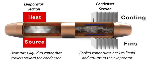
Constant conductance heat pipes (standard or CCHP) and vapor chambers are by far the most prevalent type of heat pipe used for cooling electronics. As Celsia has numerous website pages on this subject (see below), we won’t do a deep dive here. However, we’ll use this definition of a standard heat pipe when comparing them to other types: a copper enclosure with a copper sintered wick structure attached to the entirety of the inner walls of the device and a small amount of water as the working fluid.
Standard Heat Pipe Inner Workings
As with many of the other types of heat pipes, standard heat pipes can be made of different envelope materials, use different wick structures, and have alternative working fluids. However, these subjects are beyond the scope of this article.
Vapor chambers are the first type of heat pipe variation. While it’s true that the most used vapor chambers closely mimic their heat pipe cousins (copper enclosure, sintered wick, water working fluid) they are designed to function as a planar heat spreading device and need a support structure to ensure adequate vapor flow and for structural integrity under clamping loads. Heat pipes can be flattened to a width-to-height aspect ratio on the order of 4:1 while vapor chambers achieve up to 60:1 aspect ratio. This design makes them a much better heat spreader and perfect for applications where a high degree of isothermality is required.
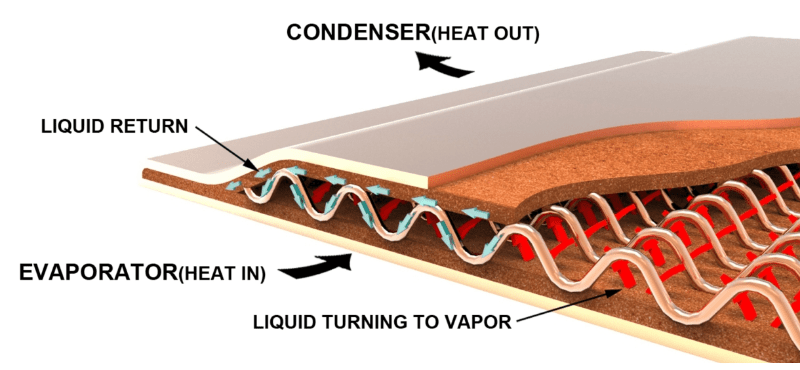
Vapor Chamber Working Principles
Variants on vapor chambers include 2-piece and 1-piece construction. The first uses a traditional manufacturing method where two stamped copper plates are bonded together, complete with wick structure, working fluid, and the addition of a support structure. A 1-piece design begins life as a very large tube (up to 70mm diameter), that’s sintered then flattened after a support structure is added. Benefits of this design include lower cost and the ability to be bent into ‘L’ and ‘U’ shapes. Here are some useful vapor chamber links:
All heat pipe variations discussed below share a few common characteristics: they use a working fluid that’s matched to the environmental operating conditions of the application, the enclosure of the ‘heat pipe’ can be made from a variety of materials but must be compatible with the working fluid, and the device is evacuated to form a vacuum allowing the working fluid to vaporize at temperatures below what would be required if at atmospheric pressure. In short, all variants are two-phase devices.
Variable Conductance Heat Pipes
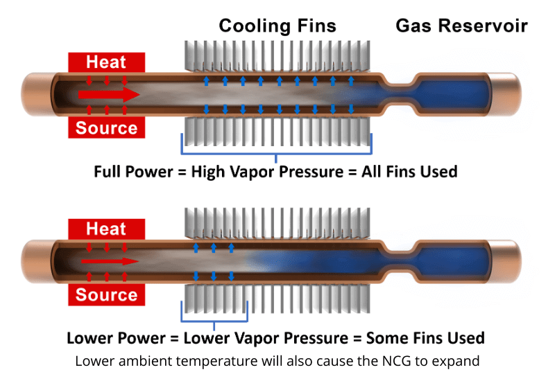
In contrast to standard heat pipes or vapor chambers (constant conductance devices), variable conductance heat pipes (VCHP) minimize temperature swings at the evaporator, usually at the lower end of the operating temperature range. Based on the power input and/or changes to the ambient temperature the device uses a varying degree of the condenser fin area by limiting the vapor space inside the heat pipe.
Variable Conductance Heat Pipe (VCHP)
In theory, it’s a remarkably simple execution. Adding a non-condensable gas (NCG), such as nitrogen or argon, to a standard heat pipe turns it into a variable conductance heat pipe. Here’s how it works. The heat pipe(s) and associated condenser (fin stack) must be designed to handle power and ambient temperature at the highest specification rating. In this instance we want the thermal solution to behave just as it would with a regular heat pipe configuration – with the working fluid vapor being able to reach the entire condenser length. Here, at the upper bounds of temperature, working fluid vapor pressure is high enough to push all the NCG to the extreme end of the heat pipe, beyond the condenser region. This allows heat to be expelled into the air using all the condenser fin area. In effect, forcing the heat sink to operate at its lowest thermal resistance.
However, when ambient temperature decreases and/or when the heat source is not at full duty cycle, the NCG expands to fill an increasing portion of the heat pipe vapor space. This prevents the lower pressure working fluid vapor from reaching some or most of the condenser fin area. The result is that the thermal solution now has a higher thermal resistance (less condenser area) so the evaporator stays warmer than it would if a standard heat pipe heat sink had been used.
In practice, these devices are extremely nuanced. As mentioned in the opening of this article, different envelopes, working fluid, and in this case, gas can be used to achieve specific results. Further, the area for the NCG can simply be at the end of a standard heat pipe (no reservoir), it can incorporate a reservoir (as shown above), or it can incorporate a flexible bladder system that expands and contracts.
Thermosiphon | Loop Thermosiphon
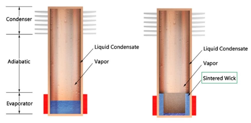
As a general rule, a thermosiphon is simply wickless heat pipes – although they sometimes include a grooved ‘wick’ that helps increase the surface area of the internal wall and allow liquid condensate to more easily return to the evaporator. Regardless, they must be used in an orientation that allows gravity to pull the liquid back to the heat source. In other words, the condenser must be above the evaporator.
Relative to standard heat pipes, thermosiphons can carry up to three times the heat transfer capacity (Qmax) for a given diameter pipe enabling a lower volume thermal solution. Further, thermosyphons can transport heat tens of meters as gravity is used for the liquid return. The functional limit for heat pipes working vertically against gravity is on the order of 150mm.
Wickless (L) and Partial Wick (R) Thermosyphons
Adding a sintered wick to the evaporator section lowers thermal resistance and increases the ability to handle higher power densities (shown above). It also allows optimization of the fluid charge, effectively reducing the required liquid. This all but eliminates the possibility of damage caused by freezing. In the figure above, note that the wick is only used at the evaporator section of the thermosyphon.
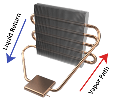
One of the limits is the interaction of the vapor and liquid condensate traveling in different directions (counter flow). To alleviate this problem, a loop thermosyphon design incorporates a separate vapor path and a liquid return path.
Loop Thermosiphon
Loop thermosyphons do not necessarily need a wick at the evaporator. However, using a wick will lower evaporation resistance and increase the maximum power density. Also, a wick can reduce the possibility of structural damage when using water as working fluid because less water is needed.
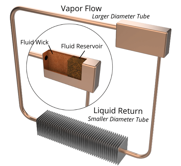
A loop heat pipe is similar to a loop thermosyphon but can operate against gravity with the evaporator above the condenser. Its operation depends on the ability of the working fluid to achieve high enough vapor pressure when heated to push the liquid condensate back to the evaporator section of the device. Unfortunately, this can’t usually be done with water as the working fluid. Instead, loop heat pipes use a refrigerant like ammonia where high pressure can be achieved at electronics operating temperatures. Typical operating temperatures for ammonia-based loop heat pipes are between -40 and 70 deg C. Generally, we see this type of device in space-related applications.
Loop Heat Pipe
The image above illustrates a loop heat pipe along with an exploded view of the wick structure inside the rectangular reservoir. With the heat source located on the back, leftward side of the reservoir, the liquid ammonia turns to vapor. Because of the wicked liquid reservoir, vapor is prevented from escaping down the right-side tube and is forced into the horizontal tube to the left. After the condenser section, the tube narrows as the size required for the liquid is quite a bit smaller than required for the vapor. Since there is no wick structure inside the tube itself, the condensate relies on the vapor pressure behind it to push it up the tube where it can be reabsorbed by the wick structure in the reservoir.
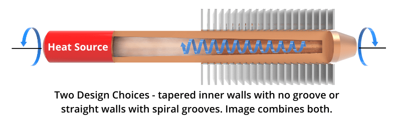
Rotating Heat Pipes
Rotating heat pipes rely on rotational force to move the liquid back to the evaporator; two different designs are typical and are both incorporated into the image below. The first uses a wickless copper tube that has a thicker, tapered wall at the condenser end. When vapor turns to liquid condensate, the centrifugal force generated by the rotating pipe pushes the liquid back to the evaporator end. The second requires spiraled grooves (much like a rifle barrel) along the inside walls which are not tapered. For cost reasons, the latter is most often the best choice. Typically, rotating heat pipes are used to remove heat generated in motors and other rotating machinery such as RF rotary joints used in telecommunications.
Rotating Heat Pipe. Two designs depicted in a single image.
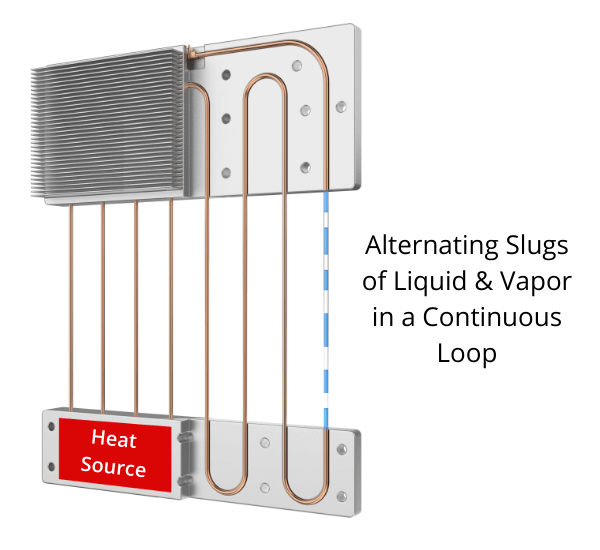
Oscillating / Pulsating Heat Pipes
First created in the early 1990’s, oscillating heat pipes are the newest member of the two-phase family. Early versions of this device (not shown) were typically a planar rectangular shape that are comprised of a lower plate into which a series of interconnected pathways are machined, and smooth upper plate that gets bonded to the lower one, air and working fluid. They are so named because of the intermittent pockets of liquid and vapor that pulsate back and forth as they move to cooler areas.
Today, much of the research on oscillating heat pipes involves designs that resemble standard heat pipe assemblies. As seen in the figure below, a wickless closed-loop tube consisting of a series of U-shaped bends is embedded in the evaporator base and condenser fins. Tubes are usually charged with either water or ethanol to between 30-80% of their volume and evacuated. As the heat is applied, vapor bubbles form creating alternating slugs of vapor and water. Further heating expands the vapor slugs, pushing the slugs of water toward the condenser, much in the same way a coffee percolator works.
Advantages of oscillating heat pipe include the ability to work over longer distances than standard heat pipes as well as very good performance when working against gravity – when the condenser is below the evaporator. Some possible disadvantages include start-up issues and operating performance at low temperatures or low power. Further, heat-carrying capacity (Qmax) and power density are lower than for other two-phase devices because the inner diameter of oscillating heat pipes is determined by the viscosity and surface tension of the working fluid so the inner tube diameter is on the smaller side.
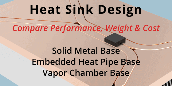
Summary – This article compares the performance, weight, and cost of three categories of heat sink design: heat sinks with a solid metal base, heat sinks with embedded heat pipe base, and heat sinks with a vapor chamber base. Heat sink fins for all designs are oriented vertically.
For more comparisons see “Heat Pipe Heat Sink Design”, which compares only heat pipe and vapor chamber designs used when the fin stack is oriented horizontally.
Engineers are regularly tasked with heat sink design optimization, making careful trade-offs between heat sink performance, weight, and cost. Sometimes the decision is easy, such as when the low-cost alternative allows the device to meet or exceed all product requirements. However, the decision is more difficult when the thermal budget is tight and/or when a single heat sink is required for different product configurations (higher power semiconductors). In these cases, alternative heat sink designs should be considered.
In this article, we’ll take a look at 5 heat sink design options (in 3 categories), each using a different configuration for the heat sink base:
Heat Sink Design Category 1: 6mm thick solid metal base (one with aluminum base & one with copper base),
Heat Sink Design Category 2: embedded heat pipes in a 6mm thick base (copper water heat pipes embedded in both a copper and aluminum base),
Heat Sink Design Category 3: 4mm thick copper/water vapor chamber base. For all options, the heat source makes direct contact with the device (no mounting plate).
Heat Sink Design Comparison: Solid Metal Base, Embedded Heat Pipe Base, Vapor Chamber Base
Further, each heat sink design is subject to the following operating parameters and performance targets:
Heat Source: 10x10mm generating 100W
Tcase Max: 80 oC
Max Ambient: 45 oC
Thermal Budget: 35 oC (80-45)
Target heat sink thermal resistance: 0.35 oC/W or less (35/100)
TIM: K = 3W/(mK)
Aluminum Fin Pack Dimensions: 150 x 99 x 30mm.
Heat Sink Fin Thickness = 0.3mm, Fin Gap = 1.2mm
Airflow: 50 CFM
Heat Sink Airflow Direction
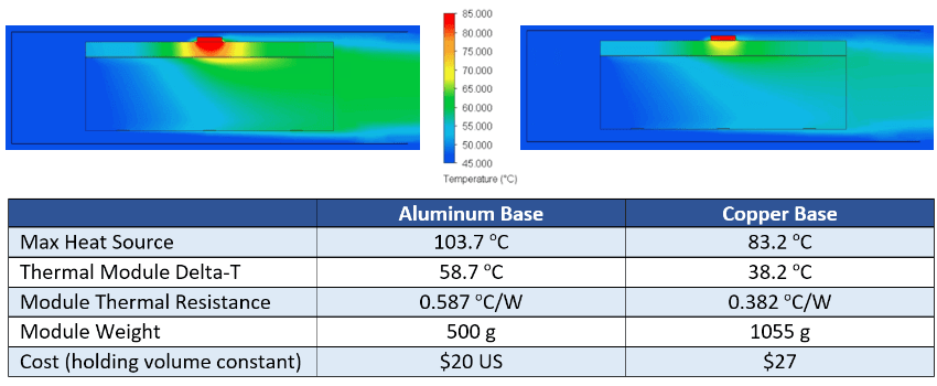
Heat Sink Design Category #1: Solid 6mm Metal Base of Either Aluminum or Copper
When evaluating any heat sink design, the single most important parameter is the thermal module delta-T relative to the calculated thermal budget (Tcase Max – Max Ambient). We know max ambient is 45 oC and if we assumed max Tcase was 80 oC, our thermal budget would be 35 oC. As a general rule, consider heat sinks designed with heat pipes or vapor chambers when the thermal budget is below 40 oC. Heat sinks with a lower delta-T will also have reduced thermal resistance.
Aluminum Base (L) and Copper Base (R) Heat Sinks
Although the aluminum and copper heat sink designs are the most cost-efficient, neither thermal module delta-T falls within the calculated thermal budget of 35 oC. If the budget was 5 degrees higher, the copper heat sink base version would meet requirements, but at a hefty weight penalty (500 vs 1,055 grams). This could be problematic as many applications have strict shock & vibration and/or portability requirements that dictate heat sink maximum weight. While not shown it the table, increasing the copper base thickness to 12mm yields a thermal module delta-t of 34.4 oC but weighs in at over 1,800 grams.
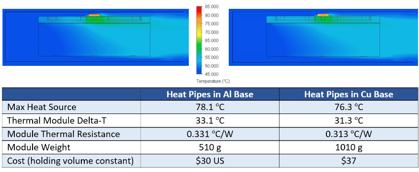
Heat Sink Design Category #2: Embedded Heat Pipes in Aluminum or Copper Base
In this heat sink design scenario, we’ve added to the heat sink base two 6mm copper/water heat pipes that have been bent and flattened to 3mm. Note that because these are direct contact heat pipes, the surface under the heat source is machined (0.025mm/cm) to ensure good contact between it and the heat source.
Embedded Heat Pipes in Aluminum Base (L) and Copper Base (R)
Compared with their solid metal base counterparts, adding heat pipes improves heat sink performance (lower delta-t and thermal resistance) by nearly 26 oC for the aluminum version and nearly 8 oC for the copper version. Here we see both heat sinks easily beating our thermal budget of 35 oC. Like our solid metal solutions, weight is roughly doubled for the copper version along with the same numeric increase in price.
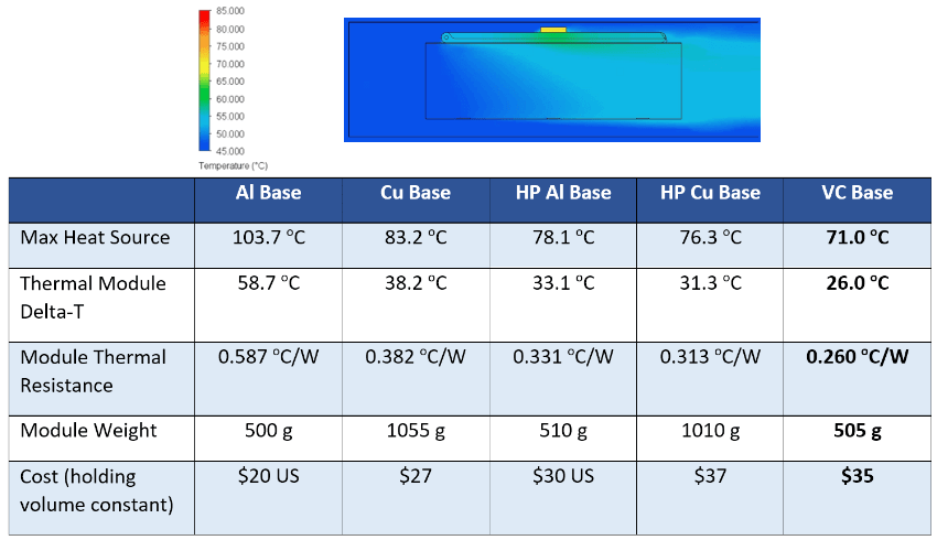
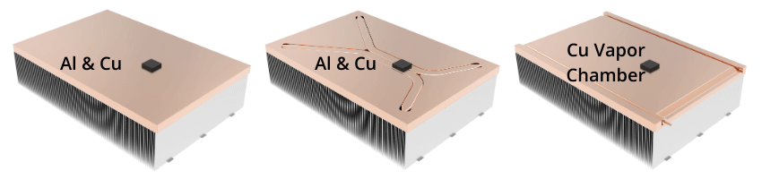
Heat Sink Design Category #3: Vapor Chamber (VC) Base
It should come as little surprise that the vapor chamber heat sink design has the lowest thermal resistance, having a delta-T at 26.0 oC – over 5 degrees cooler than the closest alternative. Moreover, the 4mm vapor chamber reduces the overall height of the heat sink by 2mm. If the designer doesn’t need the extra space, it can be added back to the fin area, further decreasing heat sink thermal resistance.
Vapor Chamber Base (far right) Compared with Alternatives
Summing up our choices, we’ve eliminated heat sink designs using a solid metal base as they do not meet thermal requirements but are the least expensive solutions. From a weight and cost perspective, the embedded heat pipe design with an aluminum base is the clear winner unless other factors are taken into account. For instance, if more powerful heat sources are slated for the same form factor and we want to maximize economies of scale for the heat sink (use the same sink across multiple product configurations), then we should calculate maximum power handling capacity without violating our thermal budget.
With a 35 oC thermal budget, we can calculate the following max heat source power input into each of the remaining options.
Of course, in doing this calculation we need to ensure the two-phase devices themselves can handle the additional power before wick dry-out occurs. In this case, both the heat pipes and the vapor chamber can do so.
Summary: This article compares 5 heat pipe heat sink designs for cost and performance:
Heat pipe heat sink with a solid aluminum base plate
Heat pipe heat sink with a solid copper base plate
Heat sink where heat pipes make direct contact with the heat source
Vapor chamber heat sink making direct contact with the heat source
3D vapor chamber heat sink making direct contact with the heat source
High-efficiency heat sink designs often include the use of heat pipes or vapor chambers. However, variations in two-phase design choices affect performance and cost significantly. Today, we’ll take a look at an application where the fins are stacked horizontally, requiring the heat pipe or vapor chamber to be routed through each of the fins. See “Heat Sink Design Options” for solid metal and heat pipe heat sink designs where the fins are vertical.
For this article, cost is based not on a nominal dollar figure (as it changes dramatically based on volume) but on the relative cost increase from one heat sink design to another. For instance, the lowest-cost solution is assigned a value of 1.0X while a heat sink that costs 20% more is assigned a value of 1.2X. This method should provide engineers with a good idea of cost premiums regardless of mass production volume.
Max Tcase: unspecified but we can assign hypothetical values to see how the thermal budget changes and what effect that has on heat pipe heat sink design choice.
Max ambient temp: 25 oC
Available airflow: 40 CFM
Condenser: zipper fin size 115*85*65 mm with fins running horizontally
For those mechanical engineers less familiar with why Max Tcase is important, here’s a quick explanation. Max Tcase temperature minus max ambient gives us the “thermal budget”. This figure must be above the heat sink Delta-t calculation to determine go/no-go performance. For instance, a thermal budget of 40 oC requires that the max heat sink delta-T from case TIM to fin-to-air temperature rise be below 40 oC.
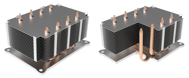
Heat Pipe Heat Sink Designs #1 and #2: Solid Aluminum vs Solid Copper Base
This is the most traditional heat pipe heat sink design. Thermal grease/pad is used between the heat source and the bottom of the solid aluminum or copper base plate. The heat pipes are soldered to the base plate. This example shows slightly flattened pipes, but round heat pipes can be used if groves for each heat pipe are cut into the base plate. A heat pipe design guide provides more detail.
U-Shaped Heat Pipe Heat Sink with Solid Aluminum or Solid Copper (not shown) Base
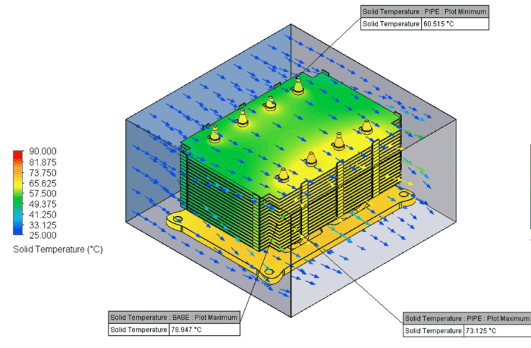
CFD of Heat Pipe Heat Sink Design with Aluminum Base
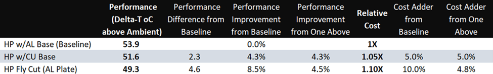
The FloTherm model for the heat sink with the aluminum mounting plate solution shows a temperature rise above ambient of 53.9 oC (78.9 – 25oC = Base Maximum – Max Ambient). Dividing the heat sink temperature rise (53.9) by the heat source power (250 watts) tells us the thermal resistance of this heat pipe heat sink: 0.2156 oC/watt. For these examples, this is the low-cost solution, so its cost baseline is 1.0X.
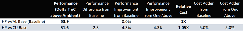
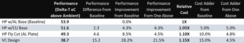
Heat Pipe Heat Sink Cost & Performance of Solid Base Designs
If more heat sink performance is required, a copper base plate can replace the aluminum one. With thermal conductivity approximately twice that of aluminum, the copper base improves heat sink performance by 2.3 oC to 51.6 oC. This design is 5% more expensive than the baseline so its relative cost adder is 1.05X that of the low-cost solution.
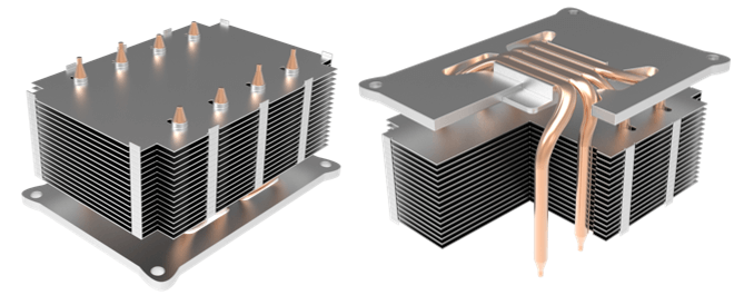
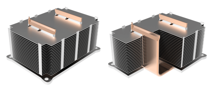
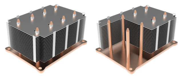
Heat Pipe Heat Sink Design #3: Direct Contact Heat Pipes
Direct Contact Heat Pipe Heat Sink
This thermal solution allows the heat source to make direct contact with the heat pipes, eliminating the base plate (in terms of conduction) and the solder interface between the heat pipes and the base plate. However, in order to achieve the necessary surface flatness, the heat pipes must be machined or fly cut, adding cost.
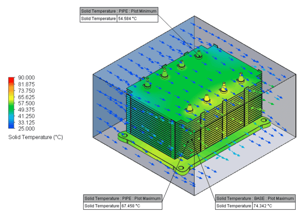
CFD Direct Contact Heat Pipes
Because the thermal pathway is reduced by one base plate and one solder interface, the delta-T of this heat pipe heat sink design improved to 49.3 oC; a 4.6 degree improvement over the baseline and a 2.3 degree improvement over the design using the copper base plate (heat sink thermal resistance = 0.1972 oC/watt). However, the additional machining of the base plate (room for HP to stick through) and machining of the heat pipes yields a cost of 1.1X that of the Baseline design (10% more expensive).
Heat Pipe Heat Sink Cost & Performance of Solid and Direct Contact Heat Pipe Bases
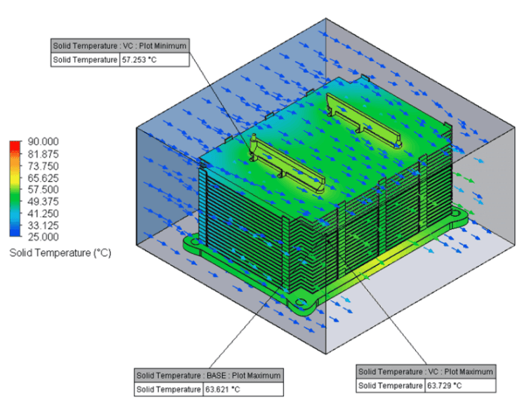
Using a U-shaped vapor chamber, this heat sink design replaces four 6mm heat pipes. It’s most similar to the direct contact heat pipe solution as both designs allow the heat source to make direct contact with the two-phase device(s). An important consideration before choosing this thermal solution is whether the heat sink supplier is able to manufacture one-piece vapor chambers because the traditional two-piece design cannot be bent into a U-shape.
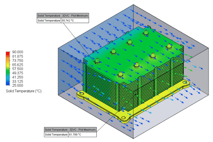
CFD U-Shaped Vapor Chamber Heat Sink
Versus the direct contact heat pipe solution, the vapor chamber thermal solution performs 21.5% better (11.6 oC lower heat sink delta-T) while only costing 4.5% more. However, the increased wall thickness of the vapor chamber drives a weight increase of around 75 grams.
Heat Pipe Heat Sink Cost & Performance of Solid and Direct Contact Bases
Heat Pipe Heat Sink Design #5: 3D Vapor Chamber
3D Vapor Chamber Heat Sink
The base plate is a vapor chamber with vertical condenser tubes sharing the same vapor space. It’s produced by brazing 8 open-ended condenser tubes to a vapor chamber with corresponding holes in it. The vapor chamber makes direct contact with the heat source spreading heat evenly along the XY planes and vertically through the condenser tubes.
CFD 3D Vapor Chamber
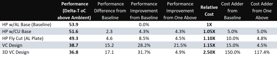
This 3D vapor chamber heat sink design has the best performance, but at a considerable cost premium. Versus its next closest competitor, the vapor chamber design, the 3D version is almost 2 degrees cooler (a 4.9% gain) but costs over twice as much (117% more).
It should be noted that this application does not fully highlight the potential benefits of a 3D vapor chamber design. As the size of the required base plate increases, the performance difference between this solution and a U-shaped vapor chamber increases as well.
Heat Pipe Heat Sink Design Cost & Performance of All Options
The table above shows that substantial performance gains are realized as materials or two-phase devices are changed. From the baseline aluminum base heat sink to the 3D vapor chamber solution, there’s a 17 oC performance improvement but cost increases by 150%.
Modest performance gains and cost adders, vs baseline, of around 7-15% are achieved by changing the base plate to a more thermally conductive copper material or by allowing the heat pipes to make direct contact with the heat source.
Given the application parameters, the best overall value is probably the U-shaped vapor chamber cooling solution. Although it’s 15% more expensive than the baseline, performance is increased by 28% (15.2 oC improvement).
In the battle of two-phase devices, vapor chamber vs heat pipe, there’s no clear winner. Each has attributes that make one superior to the other. This article covers differences in two-phase devices and usage rules of thumb. See theseheat pipe and vapor chamber links for more information on components parts and working principles.
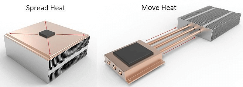
Heat Transport of Vapor Chamber vs Heat Pipe
When considering which two-phase device best fits an application, it’s best to begin with this generally accurate rule of thumb. Use vapor chambers to spread heat to a local heat sink; use heat pipes to move heat to a remote heat sink. Unlike heat pipes that move heat in a linear fashion, vapor chambers move it in multiple directions away from the heat source.
Vapor Chambers Spread Heat to Local Heat Sink | Heat Pipes Move Heat to Remote Heat Sink
It’s important to remember that the thermal conductivity of these two-phase devices change with the distance heat is moved or spread. As the distance is decreased thermal conductivity goes down, almost to the same level as solid copper, which will be a less costly option. For heat sinks using a vapor chamber, t’s generally recognized that you want the area of the vapor chamber to be at least 10 times as large as the area of the heat source. Anything much less and solid copper may be a better alternative. For heat pipe heat sinks, you want the effective heat transport length to be at least 40 -50mm.
In the end, both heat pipes and vapor chambers do an excellent job of transporting heat, it’s just that the application changes slightly. After all, the manufacturing process and working principles are functionally identical for these devices.
Heat Transport Winner: Tie
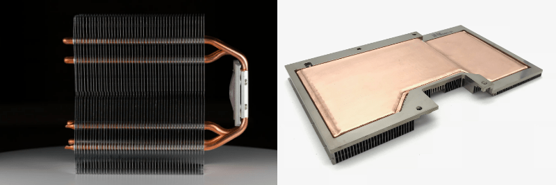
Design Flexibility of Vapor Chamber vs Heat Pipe
Think of this as the ability of vapor chambers and heat pipes to be used in a myriad of ways, depending on the thermal challenge. Heat pipes can have multiplebends to avoid components while reaching a remote heat sink, be used alone or in combination, and in different directions. In short, they are an indispensable thermal option, especially for thermal challenges involving a difficult path from the heat source to the heat sink or when the fin stack is very high, necessitating the heat pipes be run up through the fins.
Heat Pipes Offer Slightly More Design Flexibility Than Vapor Chambers
The historical design flexibility of vapor chambers was limited to the X and Y planes, with only small ‘steps’ feasible in the Z-direction. However, because the outer layer of a traditional vapor chamber is made from two stamped copper plates, almost any contiguous shape along the XY axes is possible.
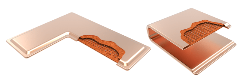
Fortunately, there is another type of vapor chamber with design flexibility in the up and down (Z) direction. Knows as 1-piece vapor chambers because they begin the manufacturing process as a very large tube (20-70mm diameter), they can be bent post-production into L and U-shapes. However, their starting shape is limited to a rectangle or a rectangle with a small portion removed.
Design Flexibility Winner: Heat Pipes (but it’s a close call)
Heat Carrying Capacity of Vapor Chamber vs Heat Pipe
Also known as Qmax, heat carrying capacity is the maximum power input (in watts) that can be applied to a heat pipe or vapor chamber and still have it work properly.
By virtue of its contiguous cross-sectional area, a single vapor chamber designed for electronics cooling can handle power input upwards of 450 watts. By contrast, the largest generally available heat pipe tops out at around 125 watts when used in the horizontal orientation (gravity neutral).
However, heat pipes are often used in combination to divvy up the heat load, whereby increasing total heat carrying capacity. To ensure each heat pipe has a relatively equal heat load, the pipes must be positioned directly above the heat source. Typically, a multiple heat pipe configuration will be close to its Qmax limit in operation while a single vapor chamber will have plenty of room to spare.
Heat Carrying Capacity Winner: Vapor Chambers
Isothermality of Vapor Chamber vs Heat Pipe
Whether spreading or moving heat, the goal for most higher-performance thermal applications is to minimize the temperature differential (delta-T) in the base of the heat sink and/or to reduce hot spots across the die face.
Minimizing the temperature gradient across the base of a heat sink is critical when the thermal budget is tight. Defined as the difference between the maximum thermal design power (TDP) of the chip minus the maximum ambient operating temperature of the device, this measurement gives us an indication of if a two-phase device should be used (usually thermal budgets less than 40 deg C).
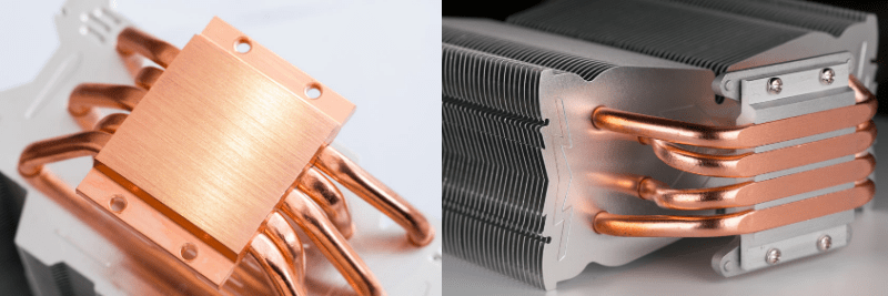
There are two commonly implemented ways heat pipe heat sinks improve isothermality when compared to solid copper, both of which relate to how the heat pipes interface with the heat source.
Indirect Interface – The most common method is a base plate of either aluminum or copper that’s mounted to the heat source which in turn conducts heat to embedded heat pipes.
Direct Interface – The second method is to mount the heat pipes directly to the heat source. This will invariably require the heat pipes to be machined to ensure good direct contact with the heat source. This method, while generally more expensive, performs better as the base plate and additional solder are removed from the heat sink assembly.
Options for Mounting Heat Pipes to the Heat Source: Indirect & Direct
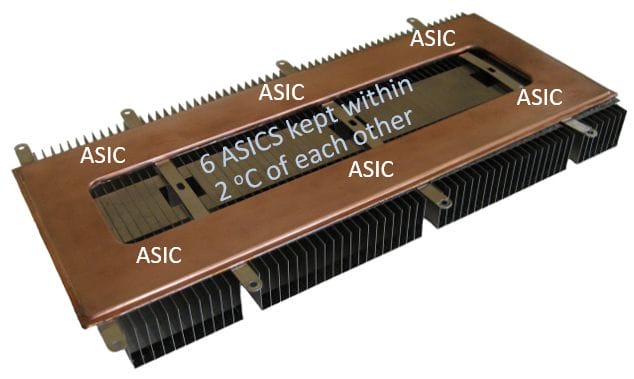
As mentioned earlier, vapor chambers have a very large internal cross-sectional area, even when compared – in practice – to multiple heat pipes embedded in the heat sink. Moreover, a vapor chamber can ‘connect’ multiple heat sources to the same heat sink and in the process create a situation where temperature differences between and around the heat sources are minimized.
6 ASICS Remain within 2 Degrees Celsius of Each Other
Lastly, shrinking microprocessor die size has resulted in ever-increasing power density that needs to be dispersed quickly. Heat pipes are typically used for applications with a power density of less than 50 W/cm2, while vapor chambers are almost a certainty when cooling power densities above 50 W/cm2.
Isothermality Winner: Vapor Chambers
Cost of Vapor Chamber vs Heat Pipe
Commercial use of heat pipes began in the 1960s at a time when, relative to today, heat loads and power densities were low. Often a single heat pipe sufficed. A vapor chamber would have been ‘overkill’. Consequently, the volume manufacturing process was refined sooner, and competition increased – driving prices down.
The traditional – two stamped copper plates – method of manufacturing vapor chambers is inherently more costly than the heat pipe method of production. Additionally, demand for vapor chambers only began to dramatically grow at the turn of the millennia due to higher power density devices.
Traditional Vapor Chamber | 1-Piece Bendable Vapor Chamber
The advent of 1-piece vapor chambers, in conjunction with the higher demand, has driven vapor chamber pricing close to parity with multiple heat pipe designs. While a few consumer applications have spawned standard-size vapor chambers, the majority of the designs are custom, lower volume projects.
In the battle of vapor chambers vs heat pipes, we have a tie if we weight the above criteria equally.
Clearly, we have a tie when comparing vapor chambers to heat pipes if all the mentioned criteria are weighted equally. In practice, thermal applications require that design engineers’ weight these differently. Most often, heat pipes prevail – that is why they represent the bulk of two-phase choices. But, when every degree counts and cost becomes slightly less important, vapor chambers win the contest.
Heat Pipes Are the Best Choice If:
Heat needs to be moved to a remote fin stack more than 40-50mm away
The thermal budget (difference between TDP and max ambient operating temperature) is below 40 0C
Nominal power densities are <50 w/cm2
Cost is a key consideration – every penny counts!
Vapor Chambers Should be Considered If:
Heat needs to be spread quickly to a heat sink base that’s 10X the area of the heat source
The thermal budget (difference between TDP and max ambient operating temperature) is below 30 0C
Multiple heat sources need to be isothermalized
Power densities are high – certainly by the time they hit 50 w/cm2
Performance is a key consideration – every degree counts!
Winner: Every Thermal Engineer
Related Links
Celsia Headquarters
22793 Dozer Lane #C9 Harbeson, DE 19951 United States Phone: (650) 667-1920 Email: admin@celsiainc.com


 Heat Sink Airflow Direction