The Truth About Ultra-Thin Heat Pipe Vapor Chambers

The Truth About Ultra-Thin Heat Pipe Vapor Chambers

The Truth About Ultra-Thin Heat Pipe Vapor Chambers

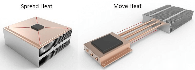
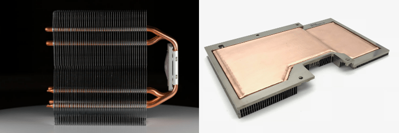
Thin and ultra-thin heat pipe vapor chambers offer excellent choices for space-constrained applications where heat needs to be moved to a remote location or spread quickly to a larger heat sink surface area. However, mechanical engineers should be mindful of the concessions that come with choosing these devices.

In this blog, we’ll break down the design variables of a heat pipe or vapor chamber, discuss each part’s purpose, and examine the implications of making each element thinner: enclosure wall thickness, wick thickness, wick type, vapor space, and internal support structures. Then, we’ll look at how each component can be changed to achieve a thinner device along with the performance impact of each change. Here, we’ll use the following definitions:

  • Thin two-phase devices
    • Heat pipes of thickness down to 1.1mm
    • Vapor chambers of thickness down to 1.55mm
  • Ultra-thin two-phase devices
    • Heat pipes of thickness down to 0.6m
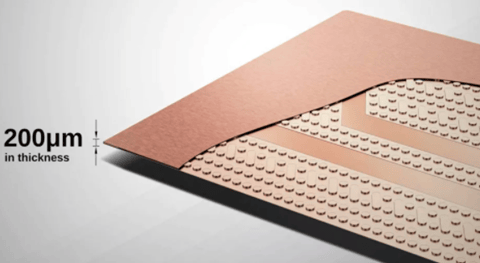
    • Vapor chambers of thickness down to 1.3mm with some experimental designs reaching 0.2mm

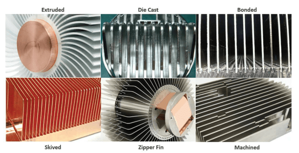
Standard and Thin Heat Pipe Vapor Chamber Component Parts

Before getting a handle on the thinned versions of heat pipe vapor chambers, let’s take a closer look at the design variables and key metrics for standard two-phase devices. If you’re feeling comfortable with this section, skip ahead.

Enclosure Wall Thickness

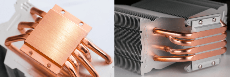
Whether made from copper (the most common), stainless steel, titanium or aluminum, a heat pipe’s enclosure wall is what gives it most of the strength needed to maintain structural integrity during nominal clamping forces of 20-60 psi against the heat source. While standard sintered wick copper heat pipes have a wall thickness between 0.1-0.3mm, vapor chamber walls are slightly thicker at between 0.3-0.5mm. The thicker walls along with an internal support structure allow vapor chambers to maintain structural integrity despite higher; aspect ratios.

Internal-Support Structure (vapor chamber only)

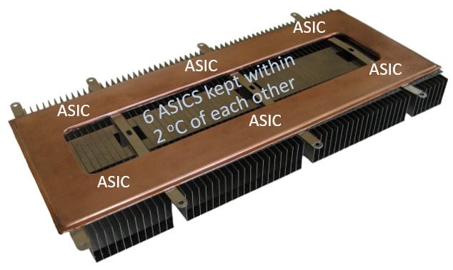
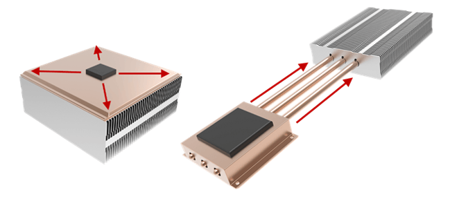
With sintered heat pipes, the width-to-height aspect ratio rarely exceeds 3:1 but for vapor chambers, we regularly produce parts with a 10 :1 ratio. The great advantage is that heat is spread in all directions over a large surface area. The disadvantage is that its structural rigidity against clamping force or accidental bump is diminished. To solve this problem, thicker walls and an internal support structure, usually in the form of vertical columns, are added to span the upper and lower divide of the internal enclosure walls. While support structures are designed to limit the reduction in vapor space, they often result in slightly reduced Qmax for many applications.

Vapor Space

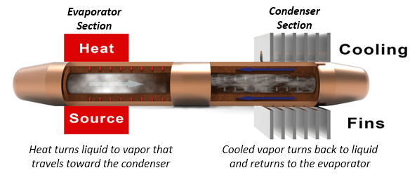
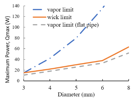
The empty space inside the thin heat pipe vapor chamber enclosure is what allows the vaporized liquid to move to areas of lower pressure – and really what gives a two-phase device its potential to move high power density with very low thermal resistance. Round heat pipes, especially those diameters above 5mm, have enough excess vapor space that flattening them slightly has no effect on Qmax. However, after a certain flattening point, Qmax will start to decrease.

Wick Thickness & Type

Heat pipe wick thickness, structure, and type all play key roles in helping move the condensed liquid from the heat sink area to the heat source area so that the two-phase cycle can continue. If the device needs to operate against gravity (heat source above heat sink) you must have a wick. The most common, most efficient, and thickest is a sintered wick followed in all categories by bundled fiber, mesh and grooved/etched wicks. As heat pipe wick thickness increases, the amount of vapor space, in many cases, is diminished resulting in reduced thermal performance.

Thin Heat Pipe Vapor Chambers

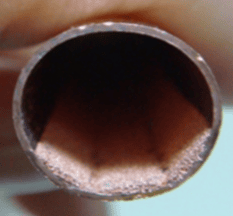
When heat pipe vapor chamber performance and flatness across a wide range of power densities and orientations are needed, a sintered wick is likely a necessity. Typical configurations for sintered wicks include, a) attached all the way around the inner walls of a thin heat pipe and b) attached to both the upper and lower plates of a thin vapor chamber. This configuration circulates the most condensed liquid back to the evaporator, an especially important consideration for operation against gravity and/or with higher power density heat sources.

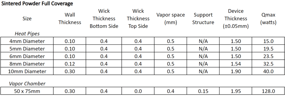
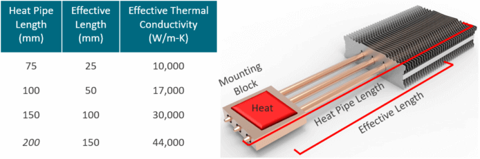
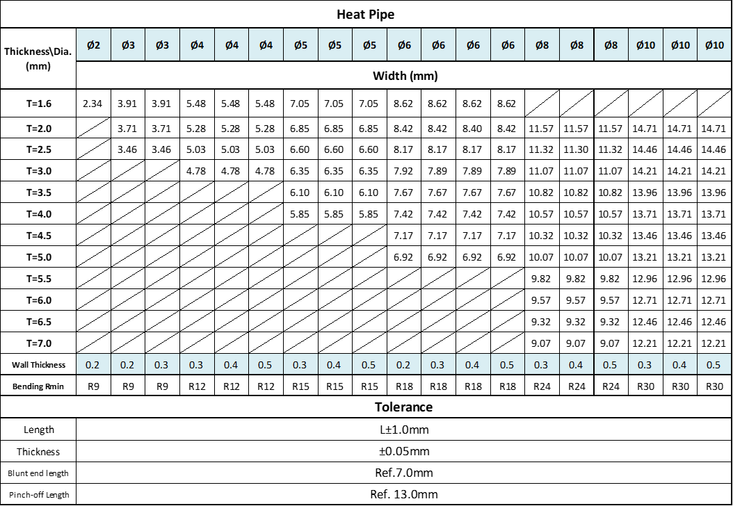
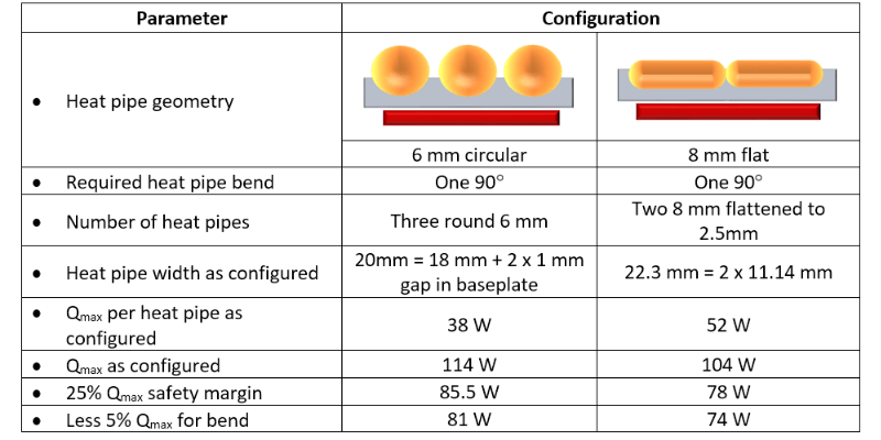
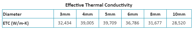
As seen in the table above, thin heat pipes and vapor chambers range in thickness from 1.5mm to nearly 2.0mm if a full coverage wick is required to ensure the most effective fluid return if the device is operating against gravity.

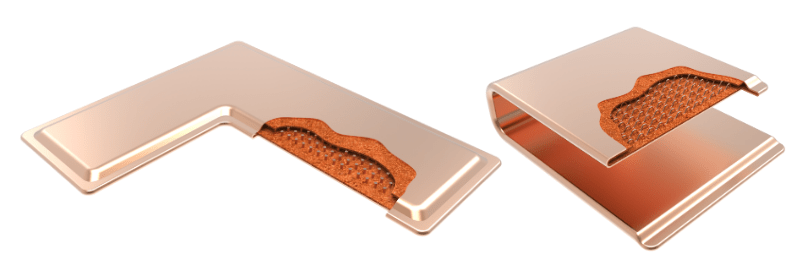
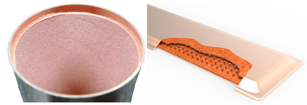
If power density, top heat pipe Qmax performance, and working against gravity are less of a concern, it’s possible to make a thinner device while keeping the same vapor space by applying the sintered wick to only the evaporator side of the device. For thin heat pipes, this means a sintered wick on slightly less than half the inner wall (before flattening) and for thin vapor chambers it means just the lower plate that contacts the evaporator will have a wick structure. See image below.

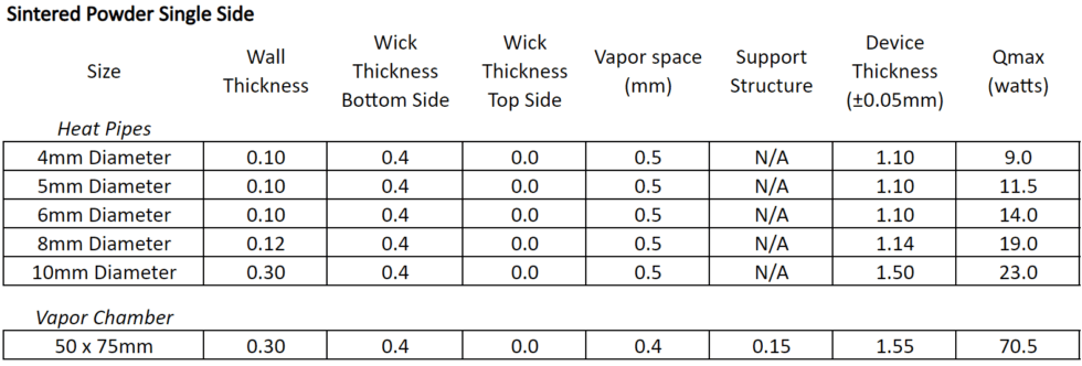
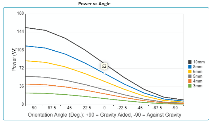
By removing the sintered wick on the top side of the thin heat pipe or vapor chamber, we’re able to reduce the overall device thickness by 0.4mm while maintaining the vapor space. In these cases, Qmax is reduced by almost half because the device is unable to return liquid to the evaporator even while operating in the horizontal orientation. An important consideration when reducing the amount of wick material is that Qmax will drop very fast as the device is required to work harder against gravity.

Ultra-Thin Heat Pipe Vapor Chambers

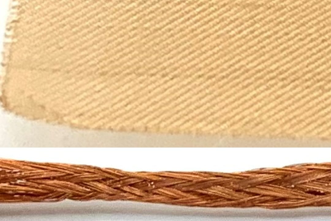
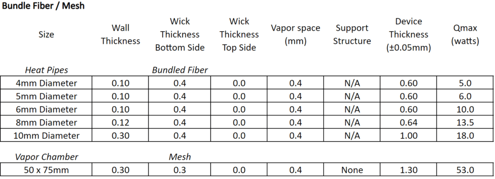
Further changes in wick structure and wall thickness are the only ways to manufacture ultra-thin heat pipes and vapor chambers. While sintered wicks allow for higher power densities (100’s of watts/sq cm2) and the ability to work against gravity, certain applications may not require these levels of performance. Let’s look at alternative wicks: bundled fiber and mesh.

Fiber bundles in the shape of a cylinder whose diameter is smaller than that of the inside diameter of the copper pipe are typically used for ultra-thin heat pipes. As the tube and bundle is squashed, vapor pockets are formed along the edges of the heat pipe, while the top, bottom, and middle contain the wick. One distinct advantage of bundled fiber over mesh is that the former allows ultra-thin heat pipes to be bent.

Mesh is often favored for vapor chambers, which are typically not bent, because it allows for greater design flexibility. The ultra-thin mesh screens have a variety of weaves to choose from as well as the ability to be used alone or in conjunction depending on the application. Further, if the device is operating with gravity (evaporator above condenser) or in the horizontal, mesh can allow for higher Qmax figures.

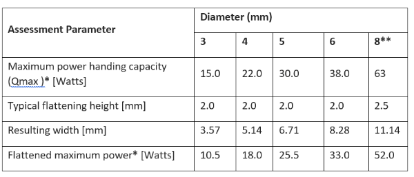
As we can see from the table below, we see ultra-thin heat pipes down to 0.6mm with vapor chambers achieving as little as 1.3mm.

Of potential concern for engineers looking to use an ultra-thin variant of heat pipes or vapor chambers is the inability of the device to carry liquid back to the evaporator beyond a 5 or so degrees adverse slope where the heat source is above the heat sink. For two-phase devices to be thinner than 0.6mm in the case of heat pipes and 1.3mm in the case of vapor chambers, further compromises must be made to both wick structure and wall thickness.

Choices for ultra-thin heat pipes and vapor chambers lead to high strength materials such as titanium or very low strength composites such as mylar/metal foil composites (image below). Both technologies have been around for decades but recently the need for spreading hot spots in low-powered consumer devices has led to the adoption of these ultra-thin, low-capacity devices.

Kelvin Thermal is an offshoot of the University of Colorado and was formed in 2014 with the goal of delivering an ultra-thin vapor chamber, which it calls a thermal ground plane and has a claimed thickness of as little as 0.15-0.25mm. A project venture between Cooler Master and Murata has touted vapor chambers down to 0.20mm. In both cases, a metal-covered plastic foil, similar to a potato chip bag, is used for the enclosure with the wick likely just an etched surface only thick enough to separate the vapor and liquid and provide a capillary path. While Qmax data is not available for specific configurations of these two-phase alternatives, it’s safe to say that power handling drops to somewhere between a few watts to perhaps as much as ten watts.
Vapor Chamber vs Heat Pipe

Vapor Chamber vs Heat Pipe

In the battle of two-phase devices, vapor chamber vs heat pipe, there’s no clear winner. Each has attributes that make one superior to the other. This article covers differences in two-phase devices and usage rules of thumb. See these heat pipe and vapor chamber links for more information on components parts and working principles. 

Heat Transport of Vapor Chamber vs Heat Pipe

When considering which two-phase device best fits an application, it’s best to begin with this generally accurate rule of thumb. Use vapor chambers to spread heat to a local heat sink; use heat pipes to move heat to a remote heat sink. Unlike heat pipes that move heat in a linear fashion, vapor chambers move it in multiple directions away from the heat source.

heat pipes move heat and vapor chambers spread heat

Vapor Chambers Spread Heat to Local Heat Sink | Heat Pipes Move Heat to Remote Heat Sink

It’s important to remember that the thermal conductivity of these two-phase devices change with the distance heat is moved or spread. As the distance is decreased thermal conductivity goes down, almost to the same level as solid copper, which will be a less costly option. For heat sinks using a vapor chamber, t’s generally recognized that you want the area of the vapor chamber to be at least 10 times as large as the area of the heat source. Anything much less and solid copper may be a better alternative. For heat pipe heat sinks, you want the effective heat transport length to be at least 40 -50mm. 

In the end, both heat pipes and vapor chambers do an excellent job of transporting heat, it’s just that the application changes slightly. After all, the manufacturing process and working principles are functionally identical for these devices. 

Heat Transport Winner: Tie

Design Flexibility of Vapor Chamber vs Heat Pipe

Think of this as the ability of vapor chambers and heat pipes to be used in a myriad of ways, depending on the thermal challenge.  Heat pipes can have multiple bends to avoid components while reaching a remote heat sink, be used alone or in combination, and in different directions.  In short, they are an indispensable thermal option, especially for thermal challenges involving a difficult path from the heat source to the heat sink or when the fin stack is very high, necessitating the heat pipes be run up through the fins. 

Compare the design flexibility of heat pipes and vapor chambers

Heat Pipes Offer Slightly More Design Flexibility Than Vapor Chambers

The historical design flexibility of vapor chambers was limited to the X and Y planes, with only small ‘steps’ feasible in the Z-direction. However, because the outer layer of a traditional vapor chamber is made from two stamped copper plates, almost any contiguous shape along the XY axes is possible. 

Fortunately, there is another type of vapor chamber with design flexibility in the up and down (Z) direction. Knows as 1-piece vapor chambers because they begin the manufacturing process as a very large tube (20-70mm diameter), they can be bent post-production into L and U-shapes. However, their starting shape is limited to a rectangle or a rectangle with a small portion removed. 

Design Flexibility Winner: Heat Pipes (but it’s a close call) 

Heat Carrying Capacity of Vapor Chamber vs Heat Pipe

Also known as Qmax, heat carrying capacity is the maximum power input (in watts) that can be applied to a heat pipe or vapor chamber and still have it work properly. 

By virtue of its contiguous cross-sectional area, a single vapor chamber designed for electronics cooling can handle power input upwards of 450 watts. By contrast, the largest generally available heat pipe tops out at around 125 watts when used in the horizontal orientation (gravity neutral). 

However, heat pipes are often used in combination to divvy up the heat load, whereby increasing total heat carrying capacity. To ensure each heat pipe has a relatively equal heat load, the pipes must be positioned directly above the heat source. Typically, a multiple heat pipe configuration will be close to its Qmax limit in operation while a single vapor chamber will have plenty of room to spare. 

Heat Carrying Capacity Winner: Vapor Chambers 

Isothermality of Vapor Chamber vs Heat Pipe

Whether spreading or moving heat, the goal for most higher-performance thermal applications is to minimize the temperature differential (delta-T) in the base of the heat sink and/or to reduce hot spots across the die face. 

Minimizing the temperature gradient across the base of a heat sink is critical when the thermal budget is tight. Defined as the difference between the maximum thermal design power (TDP) of the chip minus the maximum ambient operating temperature of the device, this measurement gives us an indication of if a two-phase device should be used (usually thermal budgets less than 40 deg C). 

There are two commonly implemented ways heat pipe heat sinks improve isothermality when compared to solid copper, both of which relate to how the heat pipes interface with the heat source. 

  • Indirect Interface – The most common method is a base plate of either aluminum or copper that’s mounted to the heat source which in turn conducts heat to embedded heat pipes.
  • Direct Interface – The second method is to mount the heat pipes directly to the heat source. This will invariably require the heat pipes to be machined to ensure good direct contact with the heat source. This method, while generally more expensive, performs better as the base plate and additional solder are removed from the heat sink assembly.
Illustrates the two options for mounting heat pipes to the heat source

Options for Mounting Heat Pipes to the Heat Source: Indirect & Direct

As mentioned earlier, vapor chambers have a very large internal cross-sectional area, even when compared – in practice – to multiple heat pipes embedded in the heat sink. Moreover, a vapor chamber can ‘connect’ multiple heat sources to the same heat sink and in the process create a situation where temperature differences between and around the heat sources are minimized. 

6 ASICS Remain within 2 Degrees Celsius of Each Other

Lastly, shrinking microprocessor die size has resulted in ever-increasing power density that needs to be dispersed quickly. Heat pipes are typically used for applications with a power density of less than 50 W/cm2, while vapor chambers are almost a certainty when cooling power densities above 50 W/cm2. 

Isothermality Winner: Vapor Chambers 

Cost of Vapor Chamber vs Heat Pipe

Commercial use of heat pipes began in the 1960s at a time when, relative to today, heat loads and power densities were low. Often a single heat pipe sufficed. A vapor chamber would have been ‘overkill’. Consequently, the volume manufacturing process was refined sooner, and competition increased – driving prices down. 

The traditional – two stamped copper plates – method of manufacturing vapor chambers is inherently more costly than the heat pipe method of production. Additionally, demand for vapor chambers only began to dramatically grow at the turn of the millennia due to higher power density devices. 

Traditional Vapor Chamber | 1-Piece Bendable Vapor Chamber

The advent of 1-piece vapor chambers, in conjunction with the higher demand, has driven vapor chamber pricing close to parity with multiple heat pipe designs. While a few consumer applications have spawned standard-size vapor chambers, the majority of the designs are custom, lower volume projects. 

Regarding relative cost and performance, we have written two blogs that compare heat pipe heat sinks to vapor chamber heat sinks for two different applications.  

For additional heat sink design tips please see Heat Pipe Design Guide and Vapor Chamber Cooling Design Guide. 

Cost Winner: Heat Pipes

Summary

In the battle of vapor chambers vs heat pipes, we have a tie if we weight the above criteria equally.

Clearly, we have a tie when comparing vapor chambers to heat pipes if all the mentioned criteria are weighted equally. In practice, thermal applications require that design engineers’ weight these differently. Most often, heat pipes prevail – that is why they represent the bulk of two-phase choices. But, when every degree counts and cost becomes slightly less important, vapor chambers win the contest. 

Heat Pipes Are the Best Choice If:

  • Heat needs to be moved to a remote fin stack more than 40-50mm away 
  • The thermal budget (difference between TDP and max ambient operating temperature) is below 40 0C 
  • Nominal power densities are <50 w/cm2 
  • Cost is a key consideration – every penny counts! 


Vapor Chambers Should be Considered If:

  • Heat needs to be spread quickly to a heat sink base that’s 10X the area of the heat source 
  • The thermal budget (difference between TDP and max ambient operating temperature) is below 30 0C 
  • Multiple heat sources need to be isothermalized 
  • Power densities are high – certainly by the time they hit 50 w/cm2 
  • Performance is a key consideration – every degree counts! 

Winner: Every Thermal Engineer

How Do Heat Pipes Work | Heat Pipes 101

How Do Heat Pipes Work | Heat Pipes 101

How Do Heat Pipes Work | Heat Pipes 101


This article covers how heat pipes and vapor chambers work along with typical uses and configuration options.  Further, it is designed to be a quick read with links to detailed information throughout the text.


How Do Heat Pipes Work?

There are three ‘parts’ to a heat pipe that allow it to work: a vacuum sealed enclosure, a wicking structure, and a working fluid. By a large margin, the most common type is a copper enclosure, a sintered copper wick structure that bonds to the interior surface, and de-ionized water as the working fluid. This configuration generally translates to non-space environments with required Max Ambient of less than 80 oC and will be the configuration presented throughout this article.

The graphic below illustrates heat pipe working principles. As heat is applied, some of the liquid turns to vapor and travels to an area of lower pressure toward the cooling fins. This allows the vapor to cool and return to liquid form where it is absorbed by the porous wick structure and transported back to the heat source via capillary action – the same principle that will soak the entirety of a paper towel if only one corner is exposed to water.


Heat Pipe Working Principles


Heat pipes are typically available in sizes from 2-12mm diameter and can be flattened and bent. Moreover, wick properties such as thickness and porosity can be changed to tune thermal performance (Qmax or maximum power carrying capacity in watts). Click here to use the online heat pipe calculator to understand Qmax by pipe size and angle of orientation. A few points:

  • Larger diameter heat pipes have higher Qmax.
  • Qmax is additive. If one pipe can carry 20W, two can carry 40W and so on.
  • Qmax is reduced when the heat pipe is bent, the capillary action is against gravity, required operating altitude above sea level increases, and often when the pipe is flattened (a small amount of flattening typically won’t affect it).

The working principles of vapor chambers are identical to heat pipes. In fact, vapor chambers are often referred to as planar heat pipes. The distinction really comes down to the width to height aspect ratio. A flattened heat pipe typically won’t exceed 4:1, whereas a vapor chamber can go up to around 60:1.


Importance of Heat Pipe Technology

You already know that heat pipes and vapor chambers are two-phase heat transfer devices used to increase the thermal performance of heat sinks that would otherwise use only a solid metal base and fins. But, what drove their mass adoption?

Put simply, heat pipes are widely used because modern electronic components have increased in thermal design power (watts of dissipated heat) and, perhaps more importantly, power density (W/cm2). With these increases, engineers realized they needed to reduce the conduction limits of solid metal. Vapor chambers and heat pipes have, in most cases, dramatically higher thermal conductivities than do solid aluminum or copper. For reference, the thermal conductivity of aluminum is ~200 W/(mK), copper is ~400 W/(mK), and two-phase devices are typically upwards of 6,000 W/(mK) – often dramatically higher.

Unlike solid metal, the effective thermal conductivity of two-phase devices changes depending on a host of variables, but mainly with the distance the heat is transferred. The longer the distance, within reason, the higher the thermal conductivity – all else being held constant. See online heat pipe performance calculator for the precise heat pipe thermal conductivity for your application. The chart below illustrates how quickly thermal conductivity increases with heat pipe length.


Heat Pipe Effective Thermal Conductivity

Heat Pipe Effective Thermal Conductivity as Function of Length


Typical Configuration & Uses

Rules of Thumb

  • Use vapor chambers to spread heat across the base of a local fin array (condenser).
  • Use heat pipes to move heat to a remote fin array or enclosure wall.


Typical usage scenario for vapor chamber and heat pipes

Vapor Chambers Spread Heat | Heat Pipes Move Heat


There are always exceptions, but here are the reasons. Heat pipes can be bent in any direction making them ideal for snaking around PCB components. This makes them well suited for moving heat to a remote condenser which most often requires some maneuvering. Conversely, vapor chambers have a continuous internal vapor space. This allows heat to be distributed in every direction to the remote corners and edges of the fin array, maximizing total fin efficiency.


Telltale Signs You Might Need a Heat Pipe or Vapor Chamber Device

Here’s a list of conditions where two-phase devices might be considered:

  • Having to move heat more than 50mm from heat source to remote condenser. Below this, solid copper bar or rods will be almost as effective.
  • When the bottom area (base) of a local fin array is greater than 10X the area of the heat source. Remember, lower air flow means larger fin area for a given heat source. This often translates to a larger base footprint as you might not have the vertical space (Z-height) and you certainly won’t have the fin efficiency to increase fin height indefinitely. See our online heat sink size calculator to get a quick estimate of the required heat sink size for your application.
  • If a solid copper heat sink (fins and base) meets thermal requirements, but not weight/shock and vibe requirements. A solid copper base is considerably heavier than a comparable vapor chamber base. Additionally, using a two-phase base may allow the use of aluminum fins, further reducing weight.
  • When thermal budgets are below 40 oC, especially when that’s coupled with low/no airflow. To calculate thermal budget, subtract the max operating temperature at which the finished device is designed to operate (Max Ambient) from the max case temperature (Tcase) of the IC – or junction temperature for bare die ICs (Tjunction). This second figure will be provided by the IC manufacturer.  You can use our online heat sink calculator to determine the total delta-T of your heat sink and compare that to your thermal budget.


Types of Heat Sinks Used with Two-Phase Devices

Lower Unit Cost – Extruded heat sinks are the most cost effective but have limited design flexibility. Die cast heat sinks are generally used as the enclosure lid with the fins exposed to the environment but high up-front tooling cost limits these to higher-volume applications.

Unique Fin Requirements – Thermal engineers sometimes need heat sinks with either very tall fins or very thin fins that are tightly spaced. Respectively, bonded fin heat sinks and skived fin heat sinks suit these requirements nicely. An advantage of bonded fin designs is that the heat sink base and the fins can be of different metals.

Most Used – What you’ll see most often paired with heat pipe or vapor chamber designs are zipper fins (also called fin packs). They are low weight and can achieve a very high fin density. Vapor chambers can be soldered to the bottom of these or heat pipes can be run through the center of the fins.  For low volume, very complicated designs where performance matters, machined heat sinks are the usual solution.


Types of Heat Sinks Used with Vapor Chambers & Heat Pipes


Related Links

Heat Pipe Thermal Conductivity

Heat Pipe Thermal Conductivity

Heat Pipe Thermal Conductivity


Knowing heat pipe thermal conductivity is important when performing Excel or CFD modeling of two-phase devices integrated into a heat sink assembly. In theory, heat pipe thermal conductivity can range from 4,000 to 100,000 W/m-K. In reality, the range for electronics cooling applications is more like 1,500 to 50,000 W/m-K. This is still an enormous improvement over the thermal conductivity of solid copper (390 W/m-K) or solid aluminum (200 W/m-K). This difference makes heat pipes an indispensable component for many of today’s high-performance heat sinks. Engineers need to confirm the thermal conductivity for each application because heat pipe thermal conductivity, unlike solid metals, varies with length (holding constant heat source power & size, and heat sink (evaporator) length.


Heat Pipe Effective Thermal Conductivity

Figure 1: Heat Pipe Effective Thermal Conductivity as Function of Length


Figure 1 illustrates the effect of length on heat pipe thermal conductivity.  In this example, three heat pipes are used to transport heat from a 75 W power source.  While thermal conductivity of 10,000 W/m.K is achieved at just under 100 mm heat pipe length, a 200 mm length has less than one-third the typically published maximum thermal conductivity of 100,000 W/m.K.  As observed in the calculation for effective thermal conductivity in equation (1), the heat pipe effective length is a function of adiabatic, evaporator and condenser lengths:

Keff = Q Leff /(A ΔT)                                                       (1)

where:

Keff = Effective thermal conductivity [W/m.K]

Q = Power transported [W]

Leff = Effective length =  (Levaporator + Lcondenser)/2 + Ladiabatic  [m]

A = Cross-sectional area [m2]

ΔT = Temperature difference between evaporator and condenser sections [°C]

You can calculate heat pipe effective thermal conductivity using our online Heat Pipe Calculator. To find vapor chamber thermal conductivity use our online Heat Sink Calculator.


Differences in Solid Metal vs Heat Pipe Thermal Conductivity

The thermal conductivity of a solid metal stays constant because it’s made up of all the same stuff, copper for instance. Consequently, each copper molecule has to pass heat to the next copper molecule. Sort of like an old-time bucket brigade. Copper thickness, length, or applied heat flux make no difference.

Heat pipe thermal conductivity, by contrast, has multiple stages of heat transfer. While it’s true that heat first needs to travel through the outer solid copper wall of the heat pipe, the heat transfer process gets accelerated during the next stage: liquid evaporation. During this stage, the working fluid, water in most cases, turns to vapor when heat is applied. And because the thermal resistance of vapor traveling down the heat pipe is so minimal it boosts thermal conductance. Moreover, the longer a distance the vapor travels (a longer heat pipe) the more the effective thermal conductivity of a heat pipe increases.


Differences in Thermal Conductivity by Heat Pipe Diameter

Holding all other variables constant, heat pipe thermal conductivity changes with diameter, but not in the direction one might expect. Small diameter heat pipes, while having a lower Qmax, have a higher effective thermal conductivity than larger diameter pipes. This is because effective thermal conductivity goes down by the ratio of the cross-sectional area. Larger diameter heat pipes have larger cross-sections. This is also the same reason a vapor chamber for a particular application will have a lower thermal conductivity than the equivalent heat pipe(s) solution.

Refer to our Heat Pipe Design Guide for more information.

Related Links

Heat Pipe Design Guide

Heat Pipe Design Guide

Heat Pipe Design Guide


The focus of this heat pipe design guide is on sintered copper heat pipes (w/water) for electronics cooling applications. This typically translates to dissipated heat of between 20-200 watts (less if power density is high) and power density up to around 25 W/cm2

This heat pipe design guide will cover the following topics:

  1. Typical Uses of Heat Pipes
  2. Heat Pipe Specifications & Tolerances
  3. Heat Pipe Performance: Sintered Copper Wick & Heat Pipe Carrying Capacity
  4. Secondary Operations Performed on Heat Pipe Designs
  5. Heat Pipe Selection Example
  6. Heat Pipe Design Guidance for Heat Sink Integration
  7. Heat Pipe Modeling Tips


Typical Uses of Heat Pipes

Used properly, and under the right conditions, heat pipes dramatically improve heat sink performance. This design reality is due to the very high thermal conductivity of heat pipes; generally between 10-100 times that of solid copper. Unlike solid metal, heat pipe thermal conductivity changes with several variables – length being the most notable. Consequently, very short heat pipes of 50mm or less have thermal properties that might be better served by using solid copper or aluminum. Here are the most common usage configurations for heat pipes as part of a heat sink assembly:

Moving Heat to a Remote Heat Sink

Heat pipes are used to move heat, in any direction or orientation, from the heat source (evaporator) to the heat sink (condenser). Pictured below are a couple of examples.


Heat Pipes Used to Move Heat to a Remote Heat Sink


Spreading Heat to a Local Heat Sink

When a two-phase device is needed yet cost is a driving factor, heat pipes can be used to spread heat to a local heat sink. A vapor chamber in either of these two applications will reduce the total heat sink delta-T by 4-9 oC . The improvement is due to the lower thermal resistance of a vapor chamber as well as the way it interfaces with the heat source (direct contact). Note that both these examples use a solid copper spreader that attaches to the heat source, then heat moves to the heat pipes (indirect contact).


Flat Heat Pipes Used to Spread Heat to a Local Heat Sink


Heat Pipe Specifications & Tolerances

The theoretical operating temperature limits of sintered copper water heat pipes are 0-250 oC, although in practice heat pipes don’t really start to operate until around 20 oC. Below 0 oC, the water freezes within the sintered wick structure but causes no damage due to expansion as the amount of liquid is so small. For example, a typical 6mm heat pipe that’s 150mm in length contains about 1cc of water.

A quick note on heat pipe reliability. Heat pipes have been extensively tested for decades. Their typical lifespan is at least 20 years and can go through thousands of freeze-thaw cycles without damage. Heat pipe failure is most likely to occur A) due to poor manufacturing processes and B) as a result of exposure to unplanned conditions: corrosive substances and unintended physical damage are the most common. Celsia mitigates the first cause of failure by helium testing every heat pipe for leakage and Qmax performance. The second cause of failure can be addressed by nickel plating the heat pipe.


List of tests performed on heat pipes and heat sink assemblies

Celsia Heat Pipe & Heat Sink Testing


The below chart provides heat pipe specifications and tolerances. Please contact us with any additional questions.


Heat Pipe Specifications & Tolerances


Heat Pipe Performance

Heat pipe carrying capacity (Qmax) is a measure of the amount of heat in watts the device can carry. It is governed, mainly, by the capillary limit of the sintered wick material whose performance can be modified by varying the thickness and/or the porosity/permeability of the wick. However, there is no one ideal wick design. It changes depending on the application requirements.

Celsia’s online Heat Pipe Calculator provides performance information based on two wick designs: standard and performance. However, we regularly design custom wick structures to precisely match customer requirements. These include the ability to vary the wick structure from one portion of the heat pipe to the next. Please contact us if you require performance figures not presented here.

The charts below show output from the heat pipe calculator using the following user-selected parameters:

  • Heat Pipe Length: 200mm
  • Evaporator Length: 25mm
  • Condenser Length: 75mm
  • Wick Type: Standard
  • Operating Temperature: 60 oC

The first chart shows heat pipe carrying capacity (Qmax) vs Angle of Operation. At +90 degrees the evaporator is directly below the condenser, at –90 the reverse is true.


Chart showing how heat pipe carrying capacity decreases as the heat pipe is required to work against gravity

Heat Pipe Carrying Capacity is Reduced When Required to Work Against Gravity


While this chart shows a nearly 90% drop-off in Qmax from +90 to -90 (standard wick), the accompanying table (not shown) gives the precise Qmax by angle. For instance, if the application requires the heat pipe to operate a no less than horizontal (0 degrees), an 8mm heat pipe will carry 62 watts of power from the heat source given the input parameters shown earlier.

The next chart (not shown) and associated table (shown) in the calculator has to do with the change in temperature (delta-T) from one end of the heat pipe to the other. This measurement is not actual length but effective length which is the heat pipe distance from the midpoint of the evaporator to the midpoint of the condenser.

Heat Pipe Thermal Resistance Calculation

Chart Used in Calculating Heat Pipe Thermal Resistance


To calculate heat pipe thermal resistance, divide its delta-T by the power input. By choosing an  8 mm heat pipe with input power of 40 oC the thermal resistance is 4.3/40 = 0.11 oC/W. Additionally, the heat pipe calculator provides the thermal conductivity for use as a necessary input to CFD programs like FloTherm. Visit this link for additional information on how to use the heat pipe calculator.


Secondary Operations to Heat Pipe Designs

Before heat pipes are integrated into a heat sink, engineers have several secondary operations to choose from.

Flattening the Heat Pipe

Typically, sintered copper heat pipes can be flattened to a maximum of between 30% to 65% of their original diameter.  However, the heat pipe carrying capacity is often negatively affected. The table below shows the Qmax for the most common heat pipe sizes which are round vs flattened.  For example, a 3mm heat pipe fattened to 2mm will have heat carrying capacity 30% less even though the pipe has only been flattened by 33%. Compare that to a 6mm heat pipe flattened to 2mm. Its Qmax is reduced by 13% even though it’s 66% flatter.


Flat Heat Pipe Power Carrying Capacity

* Horizontal Orientation

** Thicker Wall and Wick Structure

Why does flattening smaller heat pipes have more of a negative effect on Qmax?  Simply put, there are two heat pipe performance limits important for terrestrial applications: the wick limit and the vapor limit.  The wick limit is the ability of the wick to transport water from the condenser back to the evaporator.  As mentioned, the porosity and thickness of the wick can be tuned to specific applications, allowing for changes to Qmax and/or ability to work against gravity.  The vapor limit for a particular application is driven by how much space is available for the vapor to move from the evaporator to the condenser.  It is the lower of these two limits, for heat pipes that have been designed to meet application requirements, that determines Qmax.


Heat Pipe QMax is the Lesser of the Wick and Vapor Limits


The above chart illustrates this dynamic. The round 3mm heat pipe (blue and orange lines) has vapor and wick limits that are almost identical. Flatting it to 2mm results in the vapor limit below the wick limit. For a 6mm round heat pipe, there is a lot of excess vapor limit so the Qmax won’t be diminished until the pipe is reduced considerably.

Bending Heat Pipes

Bending the heat pipe will also affect the maximum power handling capacity, for which the following rules of thumb should be kept in mind.

  • First, minimum bend radius is three times the diameter of the heat pipe.
  • Second, every 45 degree bend will reduce Qmax by about 2.5%.  From Table 1, an 8 mm heat pipe, when flattened to 2.5mm, has a Qmax of 52 W.  Bending it 90 degrees would result in a further 5% reduction.  The new Qmax would be 52 – 2.55 = 49.45 W.
 
Heat Pipe Plating

Nickel plating heat pipes is done to protect against corrosion in situations where the parts are exposed to the environment. It can also be done purely for aesthetic reasons.

Heat Pipe Selection Example

Assume a 20 x 20mm heat source dissipating 70 watts of power with a single 90 degree bend – what are the appropriate heat pipe options?


Example: Choosing the Correct Size Heat Pipes


  1. To ensure each heat pipe receives the same amount of heat, place them directly above the heat source, or very nearly so. This can be done with three round 6mm heat pipes or two flattened 8mm heat pipes (flattened to 2.5mm).
  2. Make sure each pipe can handle the heat load of 70 watts. Three 6mm heat pipes can carry 38 watts each = 114 watts, while the two 8mm flat can carry a total of 104 watts.
  3. Derate the heat pipe carrying capacity by 25% (good design practice). The derated 6mm option can carry 85.5 total watts what the 8mm option can carry 78 watts.
  4. Account for bending by derating 2.5% fo the 45 degree bend. Here we have a 90 degree bend so the two options can carry 81W and 74W respectively.

As can be seen from this analysis, both heat pipe configurations are adequate to transport heat from the evaporator to the condenser.  So why choose one over the other?  From a mechanical perspective it may simply come down to heat sink stack height at the evaporator, i.e. the 8 mm configuration has a lower profile than does the 6mm configuration.  Conversely, condenser efficiency may be improved by having heat input in three locations versus two locations, necessitating the use of the 6 mm configuration.


Heat Pipe Design Guidance for Heat Sink Integration

Once the correct heat pipe(s) have been identified the next step is integration into the heat sink. When heat pipes are used to move heat (vs spread heat) this is a two-step process: heat sink integration at the evaporator and heat sink integration at the condenser.

Interface Between Heat Pipe and Heat Source (Evaporator)

There are two often used methods for connecting heat pipes with the evaporator: indirect and direct.


Heat Pipe CPU Interface | Indirect vs Direct


The more cost effective method of mating heat pipes to a heat source is usually through a base plate. This can be done with either an aluminum or copper plate (shown on left). In addition to cost advantages, this method also allows heat to be distributed more evenly to each heat pipe in situations where the heat source is much smaller that the heat pipe contact area.

Direct interface from the evaporator to the heat pipes is usually reserved for situations where the base plate and associated additional TIM layer needs to be removed for performance reasons as shown in the image to the left. This comes with cost implications as the face of the heat pipes needs to be machined in order to make the needed thermal connection with the heat source.


Interface Between Heat Pipe and Fin Stack (Condenser)

The last step is properly integrating the heat pipe(s) into the condenser portion of the heat sink. It a situation where heat pipes are being used to spread heat to a local heat sink (image below left) flattened heat pipes are soldered to the base of the heat sink


Heat Pipe Soldered to Heat Sink Base | Attached Through FIns


When moving heat to a remote condenser, there are two common heat pipe mounting configurations. The first is identical to the method above. Namely, flattened heat pipes are soldered to a flat base or round heat pipes soldered to a grooved base.  If the fin stack is large, heat will need to be distributed more evenly by running the heat pipes through the center of the fin stack as seen in the above right image.


Heat Pipe Modeling Tips

When working in a CFD program like FloTherm or developing an Excel model, there comes a point where you need to input the heat pipe effective thermal conductivity. Here’s how to find these figures using our Heat Pipe Calculator. After entering the required inputs, the first table of the Calculator provided heat pipe effective thermal conductivity figures.

When early in the modeling cycle, there’s a fairly good way to cheat if you don’t have access to this calculator. Simply multiply the power input into each heat pipe by an estimate of its thermal resistance – this will give you the estimated heat pipe delta-T. For heat pipes from 3-8mm use 0.1 oC/W  or 0.075 oC/W for larger ones. Then enter in a thermal conductivity figure (start at 4,000 W/m-K and go up) until the modeled delta-T equals the roughly calculated detla-T.


Contact Us with Questions or To Receive a Quote


Related Links