Heat Sink Types

Heat Sink Types

Heat Sink Types


In order to choose the correct heat sink for cooling electronic applications, it’s useful for engineers to understand the definitions, uses and benefits of different types of heat sinks. Here are some guidelines for the types of heat sinks that are commonly used in conjunction with heat pipes and vapor chambers. They vary by air flow, material, use of water and manufacturing process.

Heat Sinks Categorized by Airflow
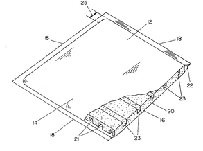
Passive Heat Sink

Passive heat sinks are those that don’t rely on forced air flow (fans)  and are considered more reliable than active solutions. A good example is a heat sink that doubles as the device enclosure. In this example, heat is moved from one or more heat generating components to one or more enclosure walls. These walls typically have a fin array exposed to the outside ambient air.


Difference between passive and active heat sink

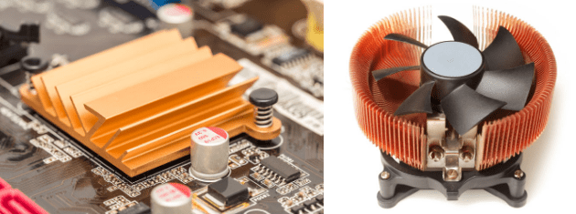
Passive Heat Sink | Active Heat Sink


Active Heat Sink

Heat sink assemblies that have a powered device such as a fan or blower in close proximity to the heat exchanger surface are active heat sinks. These would also include heat sinks that rely on pumped liquid to remove latent heat from the heat source. Because active heat sinks rely on forced air to be passed across the fin area, they are more efficient – which translates to a smaller and lighter heat sink design.

Heat Sinks Categorized by Material

Heat sink material for electronics cooling applications is almost always aluminum or copper.

Aluminum Heat Sink

Aluminum is lightweight easy to manufacture and cost effective, making it an ideal choice for most heat sinks. Alloys 6061 and 6063 are the most common alloys while 1050 and 1100 is purer with slightly higher conductivity. Its ability to move heat, thermal conductivity, is about half of copper. This limits the distance heat can be moved, conducted, away from the heat source in the base of a heat sink.

Copper Heat Sink

With a thermal conductivity of around 400 W/m-K, copper is used when heat sinks need a performance boost. Typical alloys for copper plate is CDA110 (391 w/mK). The drawback is copper is 3 times heavier and twice the cost of its aluminum counterpart. It is also slightly slower to work than aluminum. Some types of heat sinks, such as bonded fin, can be made of both materials: one for the base and the other for the fins.

Heat Sinks Categorized by Use of Water

As clumsy as this category might sound, it really just includes solid metal heat sinks assemblies, heat sinks using two-phase devices, and pumped liquid heat sinks.

Solid Metal Heat Sink

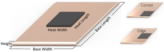
Solid metal heat sinks consist of a base into which heat is absorbed and a fin array from which heat is dissipated into the surrounding air. Depending on the heat sink manufacturing process, the base and fins can be made from different metals – copper or aluminum for electronics cooling. Typically, these are the least expensive types of heat sinks.

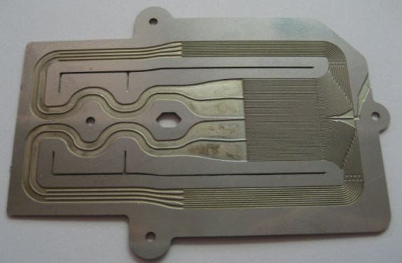
Pumped Liquid Heat Sink

Heat sinks using pumped liquid usually refer to a configuration where the pump and fin array are remote to the heat source. Liquid is pumped into a cold plate that is attached to the heat source. It then returns to the fin array to be cooled. Although very effective for removing heat it is the least reliable method of cooling electronics.


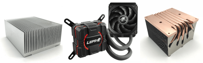
Solid Metal | Pumped | Two-Phase Heat Sinks
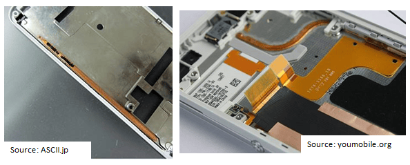
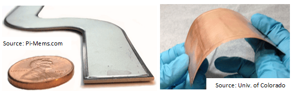
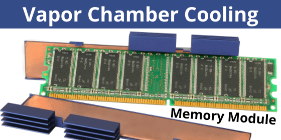
 

Two-Phase Heat Sink

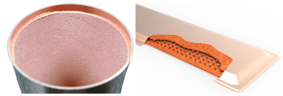
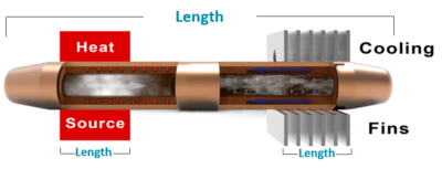
Vapor chambers and heat pipes are the most common two-phase devices and can be incorporated into heat sink assemblies to boost performance. The overall performance of the heat sink assembly is improved because of the very high thermal conductivity of these two-phase devices. Typically, heat pipes will move heat from the heat source to a remote fin array while vapor chambers are used to spread heat across the base of a local fin array. These types of heat sinks are nearly as reliable as solid metal ones while costing slightly more. Celsia specialized in this type of heat sink.

Heat Sinks by Manufacturing Process

The most common manufacturing methods for heat sinks used in conjunction with heat pipes or vapor chambers are CNC machined, forged, die cast, zipper fin, extruded, bonded, and skived.


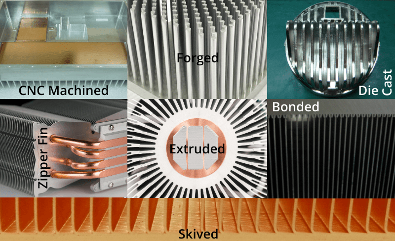
Types of Heat Sinks by Manufacturing Process


CNC Machined Heat Sink

Complex design options as well as high thermal conductivity are the two main benefits of CNC machined heat sinks. They are somewhat costly to manufacture and have a relatively slow manufacturing throughput rate, eliminating them as an option for inexpensive and/or high-volume products.

Forged & Die Cast Heat Sinks

Like forged heat sinks, die cast heat sinks offer low unit cost for high volume production. However, up front tooling cost is prohibitive for small to medium quantities. Die cast and cold forged heat sinks offer very good thermal performance. Forged heat sinks offer good design flexibility for intricate heat sinks while die cast heat sinks are limited to thicker fins making them ideal for enclosure lids used in natural convection applications.

Zipper Fin Heat Sink

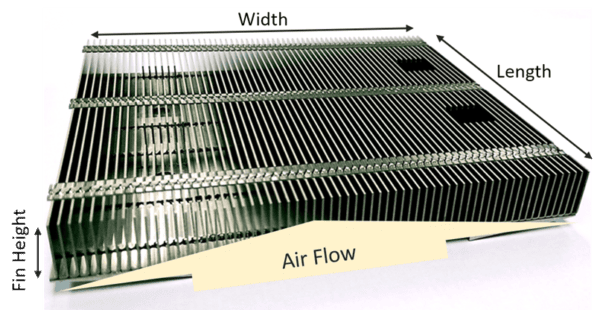
A favorite when paired with heat pipes or vapor chambers, zipper fin heat sinks are low weight and offer the ability for thin, densely packed fins and ease of integration with two-phase devices. Vapor chambers can be used as the base of the fin array while heat pipes can run through the center of the fins to efficiently dissipate heat.  Tooling cost and unit price is reasonable.

Skived Fin Heat Sink

Excellent thermal properties, thin fins, a high fin aspect ratio, and low tooling cost are the hallmarks for skived fin heat sinks. However fins can easily become bent.

Bonded Fin Heat Sink

When a very large heat sink is required, bonded fins are likely the answer. Another advantage is the base can be made of a different material than the fins.

Extruded Heat Sink

Extruded heat sinks are incredibly cost-effective yet offer limited design flexibility without secondary operations like CNC machining.

Related Links


Related Links

The Truth About Ultra-Thin Heat Pipe Vapor Chambers

The Truth About Ultra-Thin Heat Pipe Vapor Chambers

The Truth About Ultra-Thin Heat Pipe Vapor Chambers

Thin and ultra-thin heat pipe vapor chambers offer excellent choices for space-constrained applications where heat needs to be moved to a remote location or spread quickly to a larger heat sink surface area. However, mechanical engineers should be mindful of the concessions that come with choosing these devices.

In this blog, we’ll break down the design variables of a heat pipe or vapor chamber, discuss each part’s purpose, and examine the implications of making each element thinner: enclosure wall thickness, wick thickness, wick type, vapor space, and internal support structures. Then, we’ll look at how each component can be changed to achieve a thinner device along with the performance impact of each change. Here, we’ll use the following definitions:

  • Thin two-phase devices
    • Heat pipes of thickness down to 1.1mm
    • Vapor chambers of thickness down to 1.55mm
  • Ultra-thin two-phase devices
    • Heat pipes of thickness down to 0.6m
    • Vapor chambers of thickness down to 1.3mm with some experimental designs reaching 0.2mm

Standard and Thin Heat Pipe Vapor Chamber Component Parts

Before getting a handle on the thinned versions of heat pipe vapor chambers, let’s take a closer look at the design variables and key metrics for standard two-phase devices. If you’re feeling comfortable with this section, skip ahead.

Enclosure Wall Thickness

Whether made from copper (the most common), stainless steel, titanium or aluminum, a heat pipe’s enclosure wall is what gives it most of the strength needed to maintain structural integrity during nominal clamping forces of 20-60 psi against the heat source. While standard sintered wick copper heat pipes have a wall thickness between 0.1-0.3mm, vapor chamber walls are slightly thicker at between 0.3-0.5mm. The thicker walls along with an internal support structure allow vapor chambers to maintain structural integrity despite higher; aspect ratios.

Internal-Support Structure (vapor chamber only)

With sintered heat pipes, the width-to-height aspect ratio rarely exceeds 3:1 but for vapor chambers, we regularly produce parts with a 10 :1 ratio. The great advantage is that heat is spread in all directions over a large surface area. The disadvantage is that its structural rigidity against clamping force or accidental bump is diminished. To solve this problem, thicker walls and an internal support structure, usually in the form of vertical columns, are added to span the upper and lower divide of the internal enclosure walls. While support structures are designed to limit the reduction in vapor space, they often result in slightly reduced Qmax for many applications.

Vapor Space

The empty space inside the thin heat pipe vapor chamber enclosure is what allows the vaporized liquid to move to areas of lower pressure – and really what gives a two-phase device its potential to move high power density with very low thermal resistance. Round heat pipes, especially those diameters above 5mm, have enough excess vapor space that flattening them slightly has no effect on Qmax. However, after a certain flattening point, Qmax will start to decrease.

Wick Thickness & Type

Heat pipe wick thickness, structure, and type all play key roles in helping move the condensed liquid from the heat sink area to the heat source area so that the two-phase cycle can continue. If the device needs to operate against gravity (heat source above heat sink) you must have a wick. The most common, most efficient, and thickest is a sintered wick followed in all categories by bundled fiber, mesh and grooved/etched wicks. As heat pipe wick thickness increases, the amount of vapor space, in many cases, is diminished resulting in reduced thermal performance.

Thin Heat Pipe Vapor Chambers

When heat pipe vapor chamber performance and flatness across a wide range of power densities and orientations are needed, a sintered wick is likely a necessity. Typical configurations for sintered wicks include, a) attached all the way around the inner walls of a thin heat pipe and b) attached to both the upper and lower plates of a thin vapor chamber. This configuration circulates the most condensed liquid back to the evaporator, an especially important consideration for operation against gravity and/or with higher power density heat sources.

As seen in the table above, thin heat pipes and vapor chambers range in thickness from 1.5mm to nearly 2.0mm if a full coverage wick is required to ensure the most effective fluid return if the device is operating against gravity.

If power density, top heat pipe Qmax performance, and working against gravity are less of a concern, it’s possible to make a thinner device while keeping the same vapor space by applying the sintered wick to only the evaporator side of the device. For thin heat pipes, this means a sintered wick on slightly less than half the inner wall (before flattening) and for thin vapor chambers it means just the lower plate that contacts the evaporator will have a wick structure. See image below.

By removing the sintered wick on the top side of the thin heat pipe or vapor chamber, we’re able to reduce the overall device thickness by 0.4mm while maintaining the vapor space. In these cases, Qmax is reduced by almost half because the device is unable to return liquid to the evaporator even while operating in the horizontal orientation. An important consideration when reducing the amount of wick material is that Qmax will drop very fast as the device is required to work harder against gravity.

Ultra-Thin Heat Pipe Vapor Chambers

Further changes in wick structure and wall thickness are the only ways to manufacture ultra-thin heat pipes and vapor chambers. While sintered wicks allow for higher power densities (100’s of watts/sq cm2) and the ability to work against gravity, certain applications may not require these levels of performance. Let’s look at alternative wicks: bundled fiber and mesh.

Fiber bundles in the shape of a cylinder whose diameter is smaller than that of the inside diameter of the copper pipe are typically used for ultra-thin heat pipes. As the tube and bundle is squashed, vapor pockets are formed along the edges of the heat pipe, while the top, bottom, and middle contain the wick. One distinct advantage of bundled fiber over mesh is that the former allows ultra-thin heat pipes to be bent.

Mesh is often favored for vapor chambers, which are typically not bent, because it allows for greater design flexibility. The ultra-thin mesh screens have a variety of weaves to choose from as well as the ability to be used alone or in conjunction depending on the application. Further, if the device is operating with gravity (evaporator above condenser) or in the horizontal, mesh can allow for higher Qmax figures.

As we can see from the table below, we see ultra-thin heat pipes down to 0.6mm with vapor chambers achieving as little as 1.3mm.

Of potential concern for engineers looking to use an ultra-thin variant of heat pipes or vapor chambers is the inability of the device to carry liquid back to the evaporator beyond a 5 or so degrees adverse slope where the heat source is above the heat sink. For two-phase devices to be thinner than 0.6mm in the case of heat pipes and 1.3mm in the case of vapor chambers, further compromises must be made to both wick structure and wall thickness.

Choices for ultra-thin heat pipes and vapor chambers lead to high strength materials such as titanium or very low strength composites such as mylar/metal foil composites (image below). Both technologies have been around for decades but recently the need for spreading hot spots in low-powered consumer devices has led to the adoption of these ultra-thin, low-capacity devices.

Kelvin Thermal is an offshoot of the University of Colorado and was formed in 2014 with the goal of delivering an ultra-thin vapor chamber, which it calls a thermal ground plane and has a claimed thickness of as little as 0.15-0.25mm. A project venture between Cooler Master and Murata has touted vapor chambers down to 0.20mm. In both cases, a metal-covered plastic foil, similar to a potato chip bag, is used for the enclosure with the wick likely just an etched surface only thick enough to separate the vapor and liquid and provide a capillary path. While Qmax data is not available for specific configurations of these two-phase alternatives, it’s safe to say that power handling drops to somewhere between a few watts to perhaps as much as ten watts.
Heat Pipe Calculator Use Instructions

Heat Pipe Calculator Use Instructions

Heat Pipe Calculator Use Instructions


Our online heat pipe calculator provides the following heat pipe performance data: heat pipe thermal conductivity by diameter, heat pipe carrying capacity (Qmax) by diameter & orientation, and delta-T from one end of the heat pipe to the other. From this last calculation, it’s simple to arrive at the thermal resistance of the heat pipe. All calculations are for a copper heat pipe using sintered wick material and water as the working fluid.

Heat Pipe | Heat Sink Input Section

Heat Pipe Calculator Inputs

Heat PIpe Calculator Inputs

Heat Pipe Length – the full length of the heat pipe if the evaporator is at one end.

Evaporator Length – the evaporator length is the length of the actual heat source.

Condenser Length – the distance between the points where the heat pipe enters and exits the condenser.

Heat Pipe Type – Select the heat pipe wick material ‘Standard’ or ‘Performance’ sintered wick material. Standard wicks will allow you to flatten the heat pipe more before affecting the maximum power (Qmax). Note that we can alter the heat pipe wick porosity and thickness to closely match the requirements of your application, although it is not shown here.

Operating Temperature – This is the temperature of the vapor inside of the heat pipe. It is difficult to know this number and the accuracy of this input is not critical. However, use the average of the Tmax ambient and the Tmax case temperature. Sample calculation:  50 oC Max Ambient, 95 oC  Max Case  = (50 + 95)/2 = 72.5 oC Operating Temperature.

Heat Pipe Results Section

Heat Pipe Effective Thermal Conductivity

The first table calculates heat pipe effective thermal conductivity from 3-10mm diameter. We probably should have put this last as it’s used once you’ve selected the correct diameter. Nonetheless, this figure is used as input into Excel and/or CFD modeling software such as FloTHERM. 

Heat Pipe Effective Thermal Conductivity Generated from Heat Pipe Calculator

Heat Pipe Thermal Conductivity


Heat Pipe Carrying Capacity (Qmax)

Next, there is a Power vs Angle of Operation graph (shown) and corresponding table (not shown). Essentially this is giving you the maximum heat pipe carrying capacity (Qmax) of a particular diameter heat pipe at various angles.  At “+90” degrees the condenser is directly above the evaporator, making it very easy for the condensed vapor (water) to return to the evaporator, hence the high Qmax.

There are a couple of heat pipe design guidelines that will come in handy at this point.

  • First, heat pipe Qmax is additive, provided each heat pipe(s) is over the heat source. In our example, this means that one 8mm heat pipe has a Qmax of 62 oC in horizonal operation, while two 8mm pipes have a Qmax of 124 oC .
  • Second, build in a safety factor to avoid running the pipe at maximum capacity. Derating the heat pipe Qmax by 20-25% is a good industry standard – in this case a single pipe would be rated at just under 50 watts. Occasional, short power spikes above this are OK so long as they are still below the rated Qmax. 


Heat pipe power carrying capacity (Qmax)

Heat Pipe Power Carrying Capacity (Qmax)


Heat Pipe Thermal Resistance Calculation

The Power vs Delta-T graph and table (shown below) needs to be used in conjunction with the above graph. Let’s say we’ve selected the 8mm heat pipe we talked about earlier: in the horizontal position, it will safely carry just under 50 watts (after being derated).  If we put 40 watts into one end, the other end will have a delta-T of 4.3 oC (lower is better).  Let’s assume we wanted to use two 8mm heat pipes. In that case we could safely double our heat input to 80 watts. However, then using the chart we would still use the a 40 watt input figure because each heat pipe would carry 40 watts and the delta-T of each heat pipe would be the same 4.3 oC . To calculate the thermal resistance of the 8mm heat pipe, simply divide the detla-T by the input power. In this case it would be 4.3/40 = 0.11 oC  per watt.

Heat Pipe Thermal Resistance Calculation

Chart Used in Calculating Heat Pipe Thermal Resistance


Flat Heat Pipe

The last bit of information given isn’t a calculation, it’s simply some guidance on how much you can flatten heat pipes of different diameters before the Qmax will be negatively affected. The reason the performance heat pipes suffer degradation before standard pipes has to do with the thicker wick structure of the former.

We hope you find this online heat pipe calculator useful. Visit our Calculators Page to see the heat sink size and heat sink performance calculators. 

Related Links

Heat Sink Calculator Use Instructions

Heat Sink Calculator Use Instructions

Heat Sink Calculator Use Instructions


How to use the online heat sink calculator to determine heat sink performance for a thermal solution using a solid metal base compared to a vapor chamber base. Input variables include fin height, fin thickness, heat source power, and heat sink dimensions. Since fin packs (zipper fins) are often used with two-phase devices, they will be used – rather than extruded, machined, bonded, or skived heat sinks.

Here’s a link to the online calculator.

The first thing you should calculate is your thermal budget which is simply Tcase max (or Tjunction max if bare die) that will be supplied by the chip manufacturer MINUS Max Ambient temperature at which the device is designed to operate. Thermal budgets above 40 oC usually only require an aluminum or copper base whereas tighter budgets may need to add a two-phase device such as a vapor chamber.

Heat Source Power (Q) – This is the thermal design power (TDP) which is the maximum amount of heat, in watts, generated by the chip. It should be provided by the chip manufacturer or ASIC engineer if done in-house.

Heat Source Length, Width, and Location – Self-explanatory especially with the provided diagram. Remember that chip location will greatly affect base delta-t for solid metal while its effect on the vapor chamber delta-t is negligible. A general rule of thumb is that vapor chambers become attractive as the ratio of base area to heat source area surpasses 10:1.

Base Information – The length and width dimensions you enter for the base of the heat sink will also be used as the dimensions for the fin pack. It’s important to note that LENGTH (of base and fin pack) will go in the direction of the AIR FLOW. Note: if you are in the early stages of heat sink design and need an estimate of the required heat sink size, refer to this online calculator.

Fin Pack Information – While fin height can vary considerably by application, we typically see figures in the 10-35 mm range. Fin thickness for fin packs (zipper fins) range from 0.2 to 0.6 mm while fin spacing/gap should be at least 2X the fin thickness. Next, input the fin pack material and the max operating temperature at which the device is designed to operate. You can use the ‘Fin Pack Temperature Rise & Pressure Drop” chart as a starting point for selecting the appropriate fan. Conversely, if you know the fan to be used, alter the fin and air flow variables to achieve acceptable pressure drop numbers. Lastly. choose the type of TIM to be used from the drop-down menu.

The Results – The first set of delta-ts are common to both the solid metal and vapor chamber base. In this example, we have a total fin pack delta-t of 27.3 oC, and a total TIM and Base to fin delta-t of 2.5 oC.

To this total of we need to add the base delta-T.

If your thermal budget (Tcase max – Tambient max) was initially calculated at 40 oC, we see that an aluminum base, with a total heat sink delta-t of 51.4 oC will not be acceptable. While changing both the fin and solid base material to copper (not shown) will get you below the thermal budget, it comes at a large weight penalty. In this case, a vapor chamber solution is clearly the better option.


Related Links

Using Fans & Heat Pipes to Cool Smartphones

Using Fans & Heat Pipes to Cool Smartphones

Using Fans & Heat Pipes to Cool Smartphones


I recently read an interesting article that explored the practical reasons behind the use of different materials for smartphone enclosures: polycarbonate, glass, and metal. They included tactile preferences, radio attenuation, and surprisingly, thermal conductivity. While I’m pleased the mainstream press is touching on this issue, I’m sure the vast majority of smartphone users have no idea of the lengths to which engineers are going to keep these devices cool.

Smartphone Thermal Image

In addition to thermally aware power management algorithms used to scale back performance in the interest of lower temperatures, engineers are extending their thermal tool kit beyond EMI shields/spreaders and aluminum or graphite-carbon sheets to include the use of tiny fans and ultra-thin heat pipes to increase thermal efficiency.

In 2012, Apple submitted a patent application for a device that uses the phone’s vibrator motor to power a fan. While it’s yet to be implemented, the company is clearly devoting resources to tackling this problem. Additionally, Sunon is marketing a 3mm thick fan which it claims is ideal for smartphones. Given the early trend towards waterproofing hand held devices, further reducing air-flow, and the inherent problems with active cooling devices, I’m still a bit skeptical about this solution.

Fans_for_Smartphones

Smartphone Fans

I’m much more enthusiastic about the renewed activity in designing micro-thin two phase heat spreaders. For decades, the market for heat pipes and vapor chambers was almost exclusively at the high end where powers and power densities were 50-100 watts and higher into kilowatts. To handle this type of power, thickness of the two phase device must usually be greater than around 2.5mm. Early products and technical development that were thinner include the following:

  •  1980’s – Japanese heat pipe companies were selling grooved heat pipes at about 1mm while companies in the US were producing sintered wick two phase devices of 1.5mm for military applications.

Thin Two Phase Devices of the 1980s

  • 1990’s – Thermacore patent for thin-flexible heat pipes using plastic coated metal foil sheets in combination with a porous foam. Thickness in the 1mm range. Plastic Coated Metal Foil Heat Pipe
  • 2000’s – Celsia etched micro loop vapor chamber as thin as 0.7mm.

Celsia Etched Vapor Chamber 0.7mm

Within the last year and a half, NEC and Sony have both introduced smartphones using an ultra-thin heat pipe. Reported to be in the 0.6mm range at the thinnest point, these two phase devices spread and transport heat from the main processing unit. Presumably this was done to implement slightly more liberal power management techniques as well as to reduce enclosure temperature while still allowing the quad-core Snapdragon processor to perform at near peak conditions. Weight gain from switching from graphite-carbon must have seemed an acceptable trade-off.

Smartphones with Heat Pipes

NEC Medias X N-06E (L) and Sony Xperia Z2 (R)

So, where does the market stand for these products today? Most handheld OEMs are pushing the market to move to thinner solutions.  Just a few years ago 1.0 to 1.5mm was considered thin but still too thick for the consumer market. Now we’re seeing commercialized, high volume products approaching 0.5mm.

Technical papers presented on the topic show normal materials HPs and VCs made from copper, getting to 0.6mm and alternative materials going to 0.5mm and below. Pi-Mems in Santa Barbara is doing interesting work with etched Titanium as thin as 0.5mm. The strength of the titanium and it’s compatibility with water make a good combination to get to thinner structures. Additionally, The University of Colorado under Dr. Lee is miniaturizing the use of metalized plastics resulting in 0.25mm thick flexible vapor chambers. The challenge of these ultrathin structures is the pressure drop in the vapor causing high thermal resistances compared to their thicker cousins.

Micro-Thin Vapor Chambers

As with any fast moving technologies the product designers at the OEMs are in a race to move the technology forward. This drives the development of supporting technologies trying to capture these dollars.  For main stream applications in 2015, 0.6mm thick, flattened copper water heat pipes are going to be the new standard. By the following year, I’m sure it will be even thinner.

Related Links