Types of Heat Pipes

Types of Heat Pipes

This article explores the design and best uses of different types of heat pipes used for electronics cooling. These include:

  1. Standard Heat Pipes & Vapor Chambers
  2. Variable Conductance Heat Pipes (VCHP)
  3. Thermosyphon & Loop Thermosyphon
  4. Loop Heat Pipes
  5. Rotating Heat Pipes
  6. Oscillating / Pulsating Heat Pipes


Standard Heat Pipes | Vapor Chambers

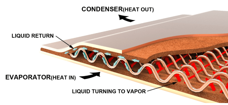
Constant conductance heat pipes (standard or CCHP) and vapor chambers are by far the most prevalent type of heat pipe used for cooling electronics.  As Celsia has numerous website pages on this subject (see below), we won’t do a deep dive here. However, we’ll use this definition of a standard heat pipe when comparing them to other types: a copper enclosure with a copper sintered wick structure attached to the entirety of the inner walls of the device and a small amount of water as the working fluid.

Diagram showing how a heat pipe works

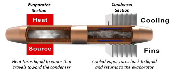
Standard Heat Pipe Inner Workings


As with many of the other types of heat pipes, standard heat pipes can be made of different envelope materials, use different wick structures, and have alternative working fluids. However, these subjects are beyond the scope of this article.

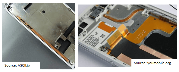
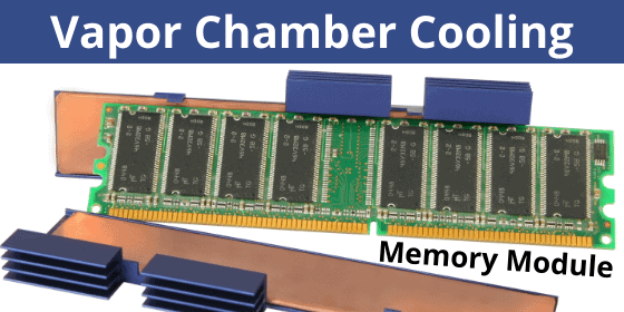
Vapor chambers are the first type of heat pipe variation. While it’s true that the most used vapor chambers closely mimic their heat pipe cousins (copper enclosure, sintered wick, water working fluid) they are designed to function as a planar heat spreading device and need a support structure to ensure adequate vapor flow and for structural integrity under clamping loads. Heat pipes can be flattened to a width-to-height aspect ratio on the order of 4:1 while vapor chambers achieve up to 60:1 aspect ratio. This design makes them a much better heat spreader and perfect for applications where a high degree of isothermality is required.

Graphic - How to Vapor Chambers Work

Vapor Chamber Working Principles


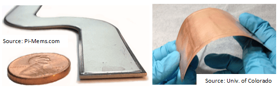
Variants on vapor chambers include 2-piece and 1-piece construction. The first uses a traditional manufacturing method where two stamped copper plates are bonded together, complete with wick structure, working fluid, and the addition of a support structure. A 1-piece design begins life as a very large tube (up to 70mm diameter), that’s sintered then flattened after a support structure is added. Benefits of this design include lower cost and the ability to be bent into ‘L’ and ‘U’ shapes. Here are some useful vapor chamber links:

All heat pipe variations discussed below share a few common characteristics: they use a working fluid that’s matched to the environmental operating conditions of the application, the enclosure of the ‘heat pipe’ can be made from a variety of materials but must be compatible with the working fluid, and the device is evacuated to form a vacuum allowing the working fluid to vaporize at temperatures below what would be required if at atmospheric pressure. In short, all variants are two-phase devices.


Variable Conductance Heat Pipes

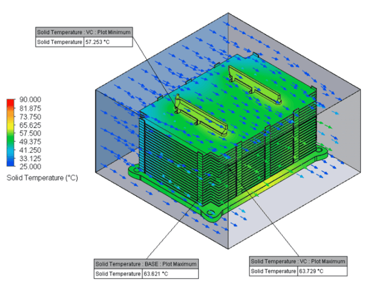
In contrast to standard heat pipes or vapor chambers (constant conductance devices), variable conductance heat pipes (VCHP) minimize temperature swings at the evaporator, usually at the lower end of the operating temperature range. Based on the power input and/or changes to the ambient temperature the device uses a varying degree of the condenser fin area by limiting the vapor space inside the heat pipe.

Diagram showing how variable conduction heat pipes work

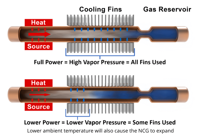
Variable Conductance Heat Pipe (VCHP)


In theory, it’s a remarkably simple execution. Adding a non-condensable gas (NCG), such as nitrogen or argon, to a standard heat pipe turns it into a variable conductance heat pipe. Here’s how it works. The heat pipe(s) and associated condenser (fin stack) must be designed to handle power and ambient temperature at the highest specification rating. In this instance we want the thermal solution to behave just as it would with a regular heat pipe configuration – with the working fluid vapor being able to reach the entire condenser length. Here, at the upper bounds of temperature, working fluid vapor pressure is high enough to push all the NCG to the extreme end of the heat pipe, beyond the condenser region. This allows heat to be expelled into the air using all the condenser fin area. In effect, forcing the heat sink to operate at its lowest thermal resistance.

However, when ambient temperature decreases and/or when the heat source is not at full duty cycle, the NCG expands to fill an increasing portion of the heat pipe vapor space. This prevents the lower pressure working fluid vapor from reaching some or most of the condenser fin area. The result is that the thermal solution now has a higher thermal resistance (less condenser area) so the evaporator stays warmer than it would if a standard heat pipe heat sink had been used.

In practice, these devices are extremely nuanced. As mentioned in the opening of this article, different envelopes, working fluid, and in this case, gas can be used to achieve specific results. Further, the area for the NCG can simply be at the end of a standard heat pipe (no reservoir), it can incorporate a reservoir (as shown above), or it can incorporate a flexible bladder system that expands and contracts.


Thermosiphon | Loop Thermosiphon

As a general rule, a thermosiphon is simply wickless heat pipes – although they sometimes include a grooved ‘wick’ that helps increase the surface area of the internal wall and allow liquid condensate to more easily return to the evaporator. Regardless, they must be used in an orientation that allows gravity to pull the liquid back to the heat source. In other words, the condenser must be above the evaporator.

Relative to standard heat pipes, thermosiphons can carry up to three times the heat transfer capacity (Qmax) for a given diameter pipe enabling a lower volume thermal solution. Further, thermosyphons can transport heat tens of meters as gravity is used for the liquid return. The functional limit for heat pipes working vertically against gravity is on the order of 150mm.

Diagram showing how thermosiphon heat pipes work

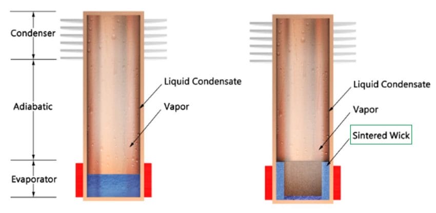
Wickless (L) and Partial Wick (R) Thermosyphons


Adding a sintered wick to the evaporator section lowers thermal resistance and increases the ability to handle higher power densities (shown above). It also allows optimization of the fluid charge, effectively reducing the required liquid. This all but eliminates the possibility of damage caused by freezing. In the figure above, note that the wick is only used at the evaporator section of the thermosyphon.

One of the limits is the interaction of the vapor and liquid condensate traveling in different directions (counter flow). To alleviate this problem, a loop thermosyphon design incorporates a separate vapor path and a liquid return path.

Diagram showing a loop thermosiphon heat pipe

Loop Thermosiphon


Loop thermosyphons do not necessarily need a wick at the evaporator. However, using a wick will lower evaporation resistance and increase the maximum power density. Also, a wick can reduce the possibility of structural damage when using water as working fluid because less water is needed.

For more information on these devices, please check out our Thermosyphon Technology Overview article.

Loop Heat Pipe

A loop heat pipe is similar to a loop thermosyphon but can operate against gravity with the evaporator above the condenser. Its operation depends on the ability of the working fluid to achieve high enough vapor pressure when heated to push the liquid condensate back to the evaporator section of the device. Unfortunately, this can’t usually be done with water as the working fluid. Instead, loop heat pipes use a refrigerant like ammonia where high pressure can be achieved at electronics operating temperatures. Typical operating temperatures for ammonia-based loop heat pipes are between -40 and 70 deg C. Generally, we see this type of device in space-related applications.
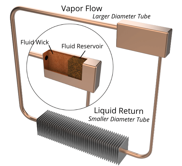
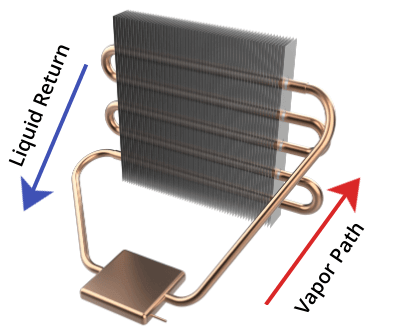
Diagram showing how a loop heat pipe works

Loop Heat Pipe


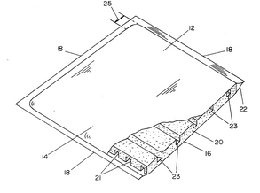
The image above illustrates a loop heat pipe along with an exploded view of the wick structure inside the rectangular reservoir. With the heat source located on the back, leftward side of the reservoir, the liquid ammonia turns to vapor. Because of the wicked liquid reservoir, vapor is prevented from escaping down the right-side tube and is forced into the horizontal tube to the left. After the condenser section, the tube narrows as the size required for the liquid is quite a bit smaller than required for the vapor. Since there is no wick structure inside the tube itself, the condensate relies on the vapor pressure behind it to push it up the tube where it can be reabsorbed by the wick structure in the reservoir.


Rotating Heat Pipes

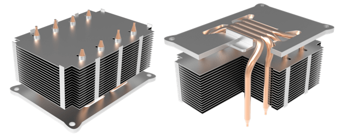
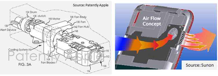
Rotating heat pipes rely on rotational force to move the liquid back to the evaporator; two different designs are typical and are both incorporated into the image below. The first uses a wickless copper tube that has a thicker, tapered wall at the condenser end. When vapor turns to liquid condensate, the centrifugal force generated by the rotating pipe pushes the liquid back to the evaporator end. The second requires spiraled grooves (much like a rifle barrel) along the inside walls which are not tapered. For cost reasons, the latter is most often the best choice. Typically, rotating heat pipes are used to remove heat generated in motors and other rotating machinery such as RF rotary joints used in telecommunications.

Diagram showing how a rotating heat pipe works

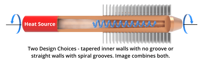
Rotating Heat Pipe. Two designs depicted in a single image.


Oscillating / Pulsating Heat Pipes

First created in the early 1990’s, oscillating heat pipes are the newest member of the two-phase family. Early versions of this device (not shown) were typically a planar rectangular shape that are comprised of a lower plate into which a series of interconnected pathways are machined, and smooth upper plate that gets bonded to the lower one, air and working fluid. They are so named because of the intermittent pockets of liquid and vapor that pulsate back and forth as they move to cooler areas.

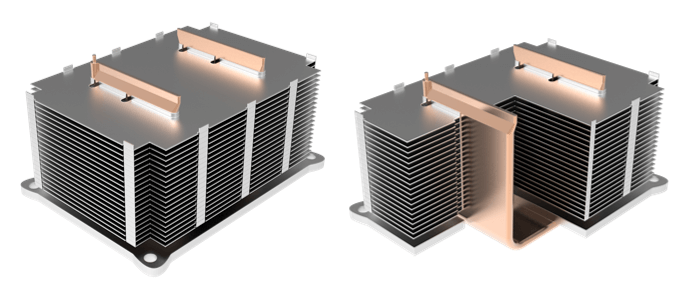
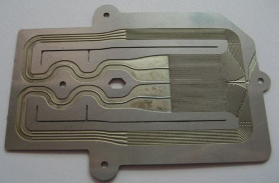
Today, much of the research on oscillating heat pipes involves designs that resemble standard heat pipe assemblies. As seen in the figure below, a wickless closed-loop tube consisting of a series of U-shaped bends is embedded in the evaporator base and condenser fins. Tubes are usually charged with either water or ethanol to between 30-80% of their volume and evacuated. As the heat is applied, vapor bubbles form creating alternating slugs of vapor and water. Further heating expands the vapor slugs, pushing the slugs of water toward the condenser, much in the same way a coffee percolator works.

Diagram showing how an oscillating heat pipe works

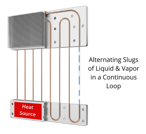
Oscillating Heat Pipe


Here’s a link to an excellent video showing an ANSYS simulation of a closed-loop oscillating heat pipe (from YouTube Channel EasyMechLearn).

Advantages of oscillating heat pipe include the ability to work over longer distances than standard heat pipes as well as very good performance when working against gravity – when the condenser is below the evaporator. Some possible disadvantages include start-up issues and operating performance at low temperatures or low power. Further, heat-carrying capacity (Qmax) and power density are lower than for other two-phase devices because the inner diameter of oscillating heat pipes is determined by the viscosity and surface tension of the working fluid so the inner tube diameter is on the smaller side.

Heat Pipe Heat Sink Design

Heat Pipe Heat Sink Design

Heat Pipe Heat Sink Design

Summary: This article compares 5 heat pipe heat sink designs for cost and performance:

  1. Heat pipe heat sink with a solid aluminum base plate
  2. Heat pipe heat sink with a solid copper base plate
  3. Heat sink where heat pipes make direct contact with the heat source
  4. Vapor chamber heat sink making direct contact with the heat source
  5. 3D vapor chamber heat sink making direct contact with the heat source

High-efficiency heat sink designs often include the use of heat pipes or vapor chambers. However, variations in two-phase design choices affect performance and cost significantly. Today, we’ll take a look at an application where the fins are stacked horizontally, requiring the heat pipe or vapor chamber to be routed through each of the fins. See “Heat Sink Design Options” for solid metal and heat pipe heat sink designs where the fins are vertical.

For this article, cost is based not on a nominal dollar figure (as it changes dramatically based on volume) but on the relative cost increase from one heat sink design to another. For instance, the lowest-cost solution is assigned a value of 1.0X while a heat sink that costs 20% more is assigned a value of 1.2X. This method should provide engineers with a good idea of cost premiums regardless of mass production volume.

Heat Pipe Heat Sink Design: Thermal Solution Parameters

  • Heat source power: 250 watts
  • Heat source size: 30×30 mm
  • Max Tcase: unspecified but we can assign hypothetical values to see how the thermal budget changes and what effect that has on heat pipe heat sink design choice.
  • Max ambient temp: 25 oC
  • Available airflow: 40 CFM
  • Condenser: zipper fin size 115*85*65 mm with fins running horizontally

For those mechanical engineers less familiar with why Max Tcase is important, here’s a quick explanation. Max Tcase temperature minus max ambient gives us the “thermal budget”. This figure must be above the heat sink Delta-t calculation to determine go/no-go performance. For instance, a thermal budget of 40 oC requires that the max heat sink delta-T from case TIM to fin-to-air temperature rise be below 40 oC.

Heat Pipe Heat Sink Designs #1 and #2: Solid Aluminum vs Solid Copper Base

This is the most traditional heat pipe heat sink design. Thermal grease/pad is used between the heat source and the bottom of the solid aluminum or copper base plate. The heat pipes are soldered to the base plate. This example shows slightly flattened pipes, but round heat pipes can be used if groves for each heat pipe are cut into the base plate. A heat pipe design guide provides more detail.


U-Shaped Heat Pipe Heat Sink with Solid Aluminum or Solid Copper (not shown) Base


CFD of Heat Pipe Heat Sink Design with Aluminum Base


The FloTherm model for the heat sink with the aluminum mounting plate solution shows a temperature rise above ambient of 53.9 oC (78.9 – 25oC = Base Maximum – Max Ambient). Dividing the heat sink temperature rise (53.9) by the heat source power (250 watts) tells us the thermal resistance of this heat pipe heat sink: 0.2156 oC/watt.  For these examples, this is the low-cost solution, so its cost baseline is 1.0X.

Heat Pipe Heat Sink Cost & Performance of Solid Base Designs

If more heat sink performance is required, a copper base plate can replace the aluminum one. With thermal conductivity approximately twice that of aluminum, the copper base improves heat sink performance by 2.3 oC to 51.6 oC. This design is 5% more expensive than the baseline so its relative cost adder is 1.05X that of the low-cost solution.


Heat Pipe Heat Sink Design #3: Direct Contact Heat Pipes


Direct Contact Heat Pipe Heat Sink


This thermal solution allows the heat source to make direct contact with the heat pipes, eliminating the base plate (in terms of conduction) and the solder interface between the heat pipes and the base plate. However, in order to achieve the necessary surface flatness, the heat pipes must be machined or fly cut, adding cost.

CFD Direct Contact Heat Pipes


Because the thermal pathway is reduced by one base plate and one solder interface, the delta-T of this heat pipe heat sink design improved to 49.3 oC; a 4.6 degree improvement over the baseline and a 2.3 degree improvement over the design using the copper base plate (heat sink thermal resistance = 0.1972 oC/watt). However, the additional machining of the base plate (room for HP to stick through) and machining of the heat pipes yields a cost of 1.1X that of the Baseline design (10% more expensive).

Heat Pipe Heat Sink Cost & Performance of Solid and Direct Contact Heat Pipe Bases


Heat Pipe Heat Sink Design #4: U-Shaped Direct Contact Vapor Chamber


U-Shaped Vapor Chamber


Using a U-shaped vapor chamber, this heat sink design replaces four 6mm heat pipes. It’s most similar to the direct contact heat pipe solution as both designs allow the heat source to make direct contact with the two-phase device(s). An important consideration before choosing this thermal solution is whether the heat sink supplier is able to manufacture one-piece vapor chambers because the traditional two-piece design cannot be bent into a U-shape.

CFD U-Shaped Vapor Chamber Heat Sink


Versus the direct contact heat pipe solution, the vapor chamber thermal solution performs 21.5% better (11.6 oC lower heat sink delta-T) while only costing 4.5% more. However, the increased wall thickness of the vapor chamber drives a weight increase of around 75 grams.

Heat Pipe Heat Sink Cost & Performance of Solid and Direct Contact Bases


Heat Pipe Heat Sink Design #5: 3D Vapor Chamber


3D Vapor Chamber Heat Sink


The base plate is a vapor chamber with vertical condenser tubes sharing the same vapor space. It’s produced by brazing 8 open-ended condenser tubes to a vapor chamber with corresponding holes in it. The vapor chamber makes direct contact with the heat source spreading heat evenly along the XY planes and vertically through the condenser tubes.


CFD 3D Vapor Chamber


This 3D vapor chamber heat sink design has the best performance, but at a considerable cost premium. Versus its next closest competitor, the vapor chamber design, the 3D version is almost 2 degrees cooler (a 4.9% gain) but costs over twice as much (117% more).

It should be noted that this application does not fully highlight the potential benefits of a 3D vapor chamber design. As the size of the required base plate increases, the performance difference between this solution and a U-shaped vapor chamber increases as well.


Heat Pipe Heat Sink Design Cost & Performance of All Options


The table above shows that substantial performance gains are realized as materials or two-phase devices are changed. From the baseline aluminum base heat sink to the 3D vapor chamber solution, there’s a 17 oC performance improvement but cost increases by 150%.

Modest performance gains and cost adders, vs baseline, of around 7-15% are achieved by changing the base plate to a more thermally conductive copper material or by allowing the heat pipes to make direct contact with the heat source.

Given the application parameters, the best overall value is probably the U-shaped vapor chamber cooling solution. Although it’s 15% more expensive than the baseline, performance is increased by 28% (15.2 oC improvement).

Using Fans & Heat Pipes to Cool Smartphones

Using Fans & Heat Pipes to Cool Smartphones

Using Fans & Heat Pipes to Cool Smartphones


I recently read an interesting article that explored the practical reasons behind the use of different materials for smartphone enclosures: polycarbonate, glass, and metal. They included tactile preferences, radio attenuation, and surprisingly, thermal conductivity. While I’m pleased the mainstream press is touching on this issue, I’m sure the vast majority of smartphone users have no idea of the lengths to which engineers are going to keep these devices cool.

Smartphone Thermal Image

In addition to thermally aware power management algorithms used to scale back performance in the interest of lower temperatures, engineers are extending their thermal tool kit beyond EMI shields/spreaders and aluminum or graphite-carbon sheets to include the use of tiny fans and ultra-thin heat pipes to increase thermal efficiency.

In 2012, Apple submitted a patent application for a device that uses the phone’s vibrator motor to power a fan. While it’s yet to be implemented, the company is clearly devoting resources to tackling this problem. Additionally, Sunon is marketing a 3mm thick fan which it claims is ideal for smartphones. Given the early trend towards waterproofing hand held devices, further reducing air-flow, and the inherent problems with active cooling devices, I’m still a bit skeptical about this solution.

Fans_for_Smartphones

Smartphone Fans

I’m much more enthusiastic about the renewed activity in designing micro-thin two phase heat spreaders. For decades, the market for heat pipes and vapor chambers was almost exclusively at the high end where powers and power densities were 50-100 watts and higher into kilowatts. To handle this type of power, thickness of the two phase device must usually be greater than around 2.5mm. Early products and technical development that were thinner include the following:

  •  1980’s – Japanese heat pipe companies were selling grooved heat pipes at about 1mm while companies in the US were producing sintered wick two phase devices of 1.5mm for military applications.

Thin Two Phase Devices of the 1980s

  • 1990’s – Thermacore patent for thin-flexible heat pipes using plastic coated metal foil sheets in combination with a porous foam. Thickness in the 1mm range. Plastic Coated Metal Foil Heat Pipe
  • 2000’s – Celsia etched micro loop vapor chamber as thin as 0.7mm.

Celsia Etched Vapor Chamber 0.7mm

Within the last year and a half, NEC and Sony have both introduced smartphones using an ultra-thin heat pipe. Reported to be in the 0.6mm range at the thinnest point, these two phase devices spread and transport heat from the main processing unit. Presumably this was done to implement slightly more liberal power management techniques as well as to reduce enclosure temperature while still allowing the quad-core Snapdragon processor to perform at near peak conditions. Weight gain from switching from graphite-carbon must have seemed an acceptable trade-off.

Smartphones with Heat Pipes

NEC Medias X N-06E (L) and Sony Xperia Z2 (R)

So, where does the market stand for these products today? Most handheld OEMs are pushing the market to move to thinner solutions.  Just a few years ago 1.0 to 1.5mm was considered thin but still too thick for the consumer market. Now we’re seeing commercialized, high volume products approaching 0.5mm.

Technical papers presented on the topic show normal materials HPs and VCs made from copper, getting to 0.6mm and alternative materials going to 0.5mm and below. Pi-Mems in Santa Barbara is doing interesting work with etched Titanium as thin as 0.5mm. The strength of the titanium and it’s compatibility with water make a good combination to get to thinner structures. Additionally, The University of Colorado under Dr. Lee is miniaturizing the use of metalized plastics resulting in 0.25mm thick flexible vapor chambers. The challenge of these ultrathin structures is the pressure drop in the vapor causing high thermal resistances compared to their thicker cousins.

Micro-Thin Vapor Chambers

As with any fast moving technologies the product designers at the OEMs are in a race to move the technology forward. This drives the development of supporting technologies trying to capture these dollars.  For main stream applications in 2015, 0.6mm thick, flattened copper water heat pipes are going to be the new standard. By the following year, I’m sure it will be even thinner.

Related Links