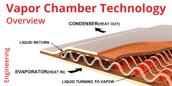
Vapor Chamber vs Heat Pipe

In the battle of two-phase devices, vapor chamber vs heat pipe, there’s no clear winner. Each has attributes that make one superior to the other. This article covers differences in two-phase devices and usage rules of thumb. See these heat pipe and vapor chamber links for more information on components parts and working principles.
Heat Transport of Vapor Chamber vs Heat Pipe
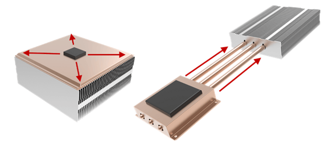
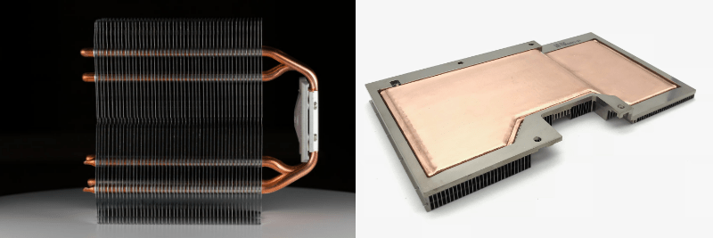
When considering which two-phase device best fits an application, it’s best to begin with this generally accurate rule of thumb. Use vapor chambers to spread heat to a local heat sink; use heat pipes to move heat to a remote heat sink. Unlike heat pipes that move heat in a linear fashion, vapor chambers move it in multiple directions away from the heat source.
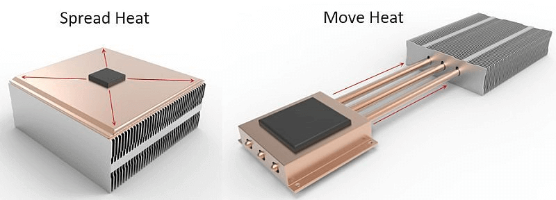
Vapor Chambers Spread Heat to Local Heat Sink | Heat Pipes Move Heat to Remote Heat Sink
It’s important to remember that the thermal conductivity of these two-phase devices change with the distance heat is moved or spread. As the distance is decreased thermal conductivity goes down, almost to the same level as solid copper, which will be a less costly option. For heat sinks using a vapor chamber, t’s generally recognized that you want the area of the vapor chamber to be at least 10 times as large as the area of the heat source. Anything much less and solid copper may be a better alternative. For heat pipe heat sinks, you want the effective heat transport length to be at least 40 -50mm.
In the end, both heat pipes and vapor chambers do an excellent job of transporting heat, it’s just that the application changes slightly. After all, the manufacturing process and working principles are functionally identical for these devices.
Heat Transport Winner: Tie
Design Flexibility of Vapor Chamber vs Heat Pipe
Think of this as the ability of vapor chambers and heat pipes to be used in a myriad of ways, depending on the thermal challenge. Heat pipes can have multiple bends to avoid components while reaching a remote heat sink, be used alone or in combination, and in different directions. In short, they are an indispensable thermal option, especially for thermal challenges involving a difficult path from the heat source to the heat sink or when the fin stack is very high, necessitating the heat pipes be run up through the fins.
Heat Pipes Offer Slightly More Design Flexibility Than Vapor Chambers
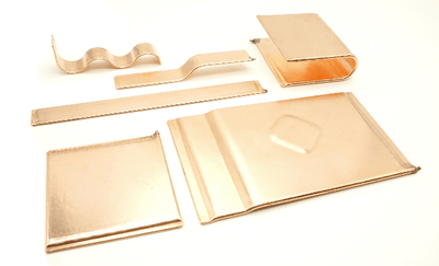
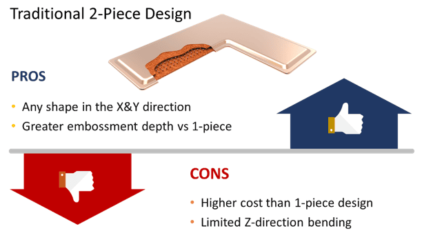
The historical design flexibility of vapor chambers was limited to the X and Y planes, with only small ‘steps’ feasible in the Z-direction. However, because the outer layer of a traditional vapor chamber is made from two stamped copper plates, almost any contiguous shape along the XY axes is possible.
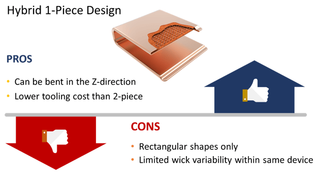
Fortunately, there is another type of vapor chamber with design flexibility in the up and down (Z) direction. Knows as 1-piece vapor chambers because they begin the manufacturing process as a very large tube (20-70mm diameter), they can be bent post-production into L and U-shapes. However, their starting shape is limited to a rectangle or a rectangle with a small portion removed.
Design Flexibility Winner: Heat Pipes (but it’s a close call)
Heat Carrying Capacity of Vapor Chamber vs Heat Pipe
Also known as Qmax, heat carrying capacity is the maximum power input (in watts) that can be applied to a heat pipe or vapor chamber and still have it work properly.
By virtue of its contiguous cross-sectional area, a single vapor chamber designed for electronics cooling can handle power input upwards of 450 watts. By contrast, the largest generally available heat pipe tops out at around 125 watts when used in the horizontal orientation (gravity neutral).
However, heat pipes are often used in combination to divvy up the heat load, whereby increasing total heat carrying capacity. To ensure each heat pipe has a relatively equal heat load, the pipes must be positioned directly above the heat source. Typically, a multiple heat pipe configuration will be close to its Qmax limit in operation while a single vapor chamber will have plenty of room to spare.
Heat Carrying Capacity Winner: Vapor Chambers
Isothermality of Vapor Chamber vs Heat Pipe
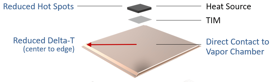
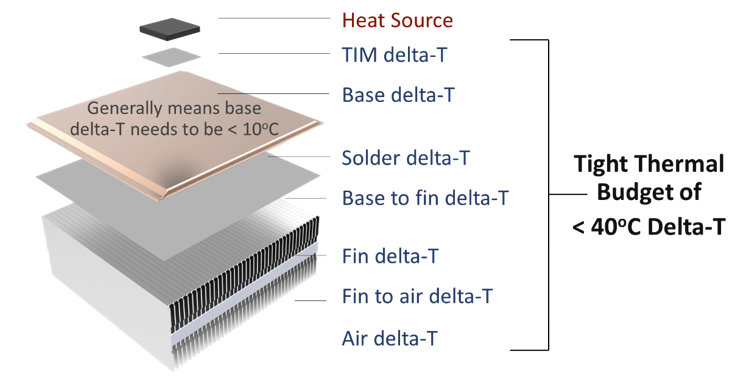
Whether spreading or moving heat, the goal for most higher-performance thermal applications is to minimize the temperature differential (delta-T) in the base of the heat sink and/or to reduce hot spots across the die face.
Minimizing the temperature gradient across the base of a heat sink is critical when the thermal budget is tight. Defined as the difference between the maximum thermal design power (TDP) of the chip minus the maximum ambient operating temperature of the device, this measurement gives us an indication of if a two-phase device should be used (usually thermal budgets less than 40 deg C).
There are two commonly implemented ways heat pipe heat sinks improve isothermality when compared to solid copper, both of which relate to how the heat pipes interface with the heat source.
- Indirect Interface – The most common method is a base plate of either aluminum or copper that’s mounted to the heat source which in turn conducts heat to embedded heat pipes.
- Direct Interface – The second method is to mount the heat pipes directly to the heat source. This will invariably require the heat pipes to be machined to ensure good direct contact with the heat source. This method, while generally more expensive, performs better as the base plate and additional solder are removed from the heat sink assembly.
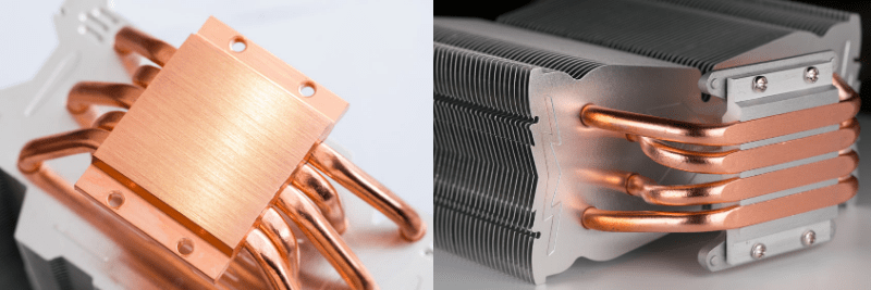
Options for Mounting Heat Pipes to the Heat Source: Indirect & Direct
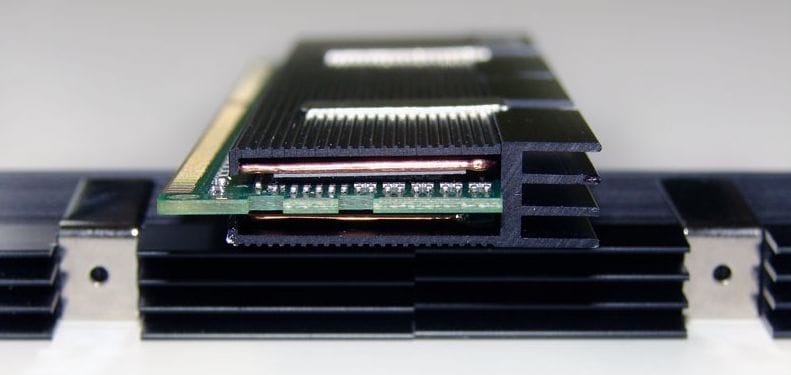
As mentioned earlier, vapor chambers have a very large internal cross-sectional area, even when compared – in practice – to multiple heat pipes embedded in the heat sink. Moreover, a vapor chamber can ‘connect’ multiple heat sources to the same heat sink and in the process create a situation where temperature differences between and around the heat sources are minimized.
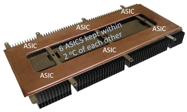
6 ASICS Remain within 2 Degrees Celsius of Each Other
Lastly, shrinking microprocessor die size has resulted in ever-increasing power density that needs to be dispersed quickly. Heat pipes are typically used for applications with a power density of less than 50 W/cm2, while vapor chambers are almost a certainty when cooling power densities above 50 W/cm2.
Isothermality Winner: Vapor Chambers
Cost of Vapor Chamber vs Heat Pipe
Commercial use of heat pipes began in the 1960s at a time when, relative to today, heat loads and power densities were low. Often a single heat pipe sufficed. A vapor chamber would have been ‘overkill’. Consequently, the volume manufacturing process was refined sooner, and competition increased – driving prices down.
The traditional – two stamped copper plates – method of manufacturing vapor chambers is inherently more costly than the heat pipe method of production. Additionally, demand for vapor chambers only began to dramatically grow at the turn of the millennia due to higher power density devices.
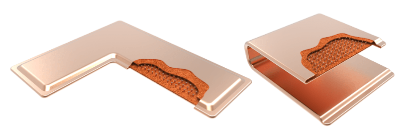
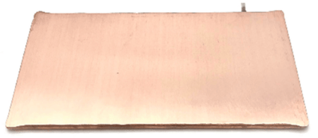
Traditional Vapor Chamber | 1-Piece Bendable Vapor Chamber
The advent of 1-piece vapor chambers, in conjunction with the higher demand, has driven vapor chamber pricing close to parity with multiple heat pipe designs. While a few consumer applications have spawned standard-size vapor chambers, the majority of the designs are custom, lower volume projects.
Regarding relative cost and performance, we have written two blogs that compare heat pipe heat sinks to vapor chamber heat sinks for two different applications.
For additional heat sink design tips please see Heat Pipe Design Guide and Vapor Chamber Cooling Design Guide.
Cost Winner: Heat Pipes
Summary
In the battle of vapor chambers vs heat pipes, we have a tie if we weight the above criteria equally.
Clearly, we have a tie when comparing vapor chambers to heat pipes if all the mentioned criteria are weighted equally. In practice, thermal applications require that design engineers’ weight these differently. Most often, heat pipes prevail – that is why they represent the bulk of two-phase choices. But, when every degree counts and cost becomes slightly less important, vapor chambers win the contest.
Heat Pipes Are the Best Choice If:
- Heat needs to be moved to a remote fin stack more than 40-50mm away
- The thermal budget (difference between TDP and max ambient operating temperature) is below 40 0C
- Nominal power densities are <50 w/cm2
- Cost is a key consideration – every penny counts!
Vapor Chambers Should be Considered If:
- Heat needs to be spread quickly to a heat sink base that’s 10X the area of the heat source
- The thermal budget (difference between TDP and max ambient operating temperature) is below 30 0C
- Multiple heat sources need to be isothermalized
- Power densities are high – certainly by the time they hit 50 w/cm2
- Performance is a key consideration – every degree counts!
Winner: Every Thermal Engineer