Bending Heat Pipes | How it Affects Vapor Chambers & Heat Pipes
Bending Heat Pipes | How it Affects Vapor Chambers & Heat Pipes
The majority of applications for heat pipes, and to a lesser extent vapor chambers, require these products to be bent. Below are respective examples for high-performance graphics card, semiconductor equipment and networking applications.

Figure 1: Heat Sinks Using Bent Two-Phase Devices
But what effect does bending a heat pipe or vapor chamber have on their performance? To answer this, let’s first talk about bend parameters then we’ll move into the meat of it and discuss both evaporator and vapor resistances.
Although smaller bend radii are possible, heat pipe guidelines almost universally put their c/l (centerline) bend radius at 3X the diameter of the heat pipe being bent. In other words, for a 5mm round heat pipe bent into a U shape, the resulting OD would be 35mm.
Bend radius for a 1.5-3.5mm thick vapor chambers are about 10mm. For instance, for a 2mm thick vapor chamber the OD of a 180 degree bend would be 22mm. While these would have to stamped into place for a traditional two-piece vapor chamber, one-piece designs can be bent post production, even into a U-shape.
Two areas of thermal resistance in these devices must be closely examined. The first is evaporation resistance which is the deta-t due to conduction through the device wall and wick structure as well as phase change of the working fluid into vapor.
In the vast majority of applications, the evaporation resistance is the dominate resistance; therefore, making these devices somewhat length independent. This means that a two-phase device with a transport distance of 75 mm will have almost the same Tsource -Tsink as one with a 150 mm transport distance. This, in effect, doubles the effective thermal conductivity for the longer devices. For a typical water/copper heat pipe with 0.5mm wall and 0.4mm sintered wick, thermal resistance has a nominal value of about 0.1 oC/w/cm2
The second is vapor transport resistance which is the temperature loss in the transport region due to pressure drop and condensation delta-t’s. This resistance is typically a function of the power density in the vapor space – nominal power densities are 300-400 w/cm2 with a typical maximum of 800-1,000 w/cm2. The nominal thermal resistance of vapor transport is about 0.01o C/w/cm2. Because of the correlation between cross sectional area of the vapor space and vapor resistance, smaller diameter heat pipes or those that have been flattened increases vapor flow thermal resistance.
So how are these two key resistances affected by bending a two-phase device?
Because the evaporator is almost never placed at the arch of a bent two-phase device, we would expect relatively little to no increase in its nominal value when comparing straight and bend two-phase devices. When testing a 3mm thick U-shaped vapor chamber with a 10mm bend radius we see this to be true. Test data showing the evaporation resistance before and after bending is shown in Figure 4. The results are identical within measurement error.
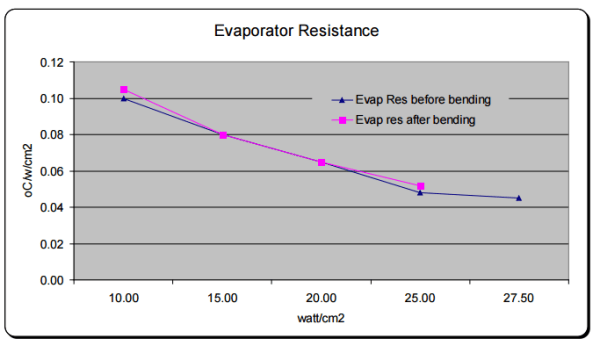
Figure 4: Evaporator Resistance
Now let’s look at vapor transport resistance. Due to the pressure drop induced by bending the vapor chamber, we would expect vapor transport resistance to increase due to an increase in pressure drop, thus decreasing the thermal conductivity of the device. Again, testing supports this claim and is relatively consistent between heat pipes and vapor chambers. Bending a two-phase device 180 degrees increases vapor flow resistance by around 50%.
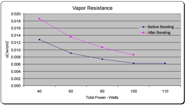
Figure 5: Vapor Resistance
It’s important to note that while vapor transport resistance is significantly affected by bending, its relative contribution to overall thermal resistance is often small. Remember that for an un-bent part, evaporator resistance is a full order of magnitude greater than that of vapor flow resistance.
So, when we examine the overall thermal resistance, we see that the net effect is between 18-40%. You will also note a decrease in the total power. When relying on capillary pumping in the wick structure to return the fluid the bending affects the pore radius and porosity in the bend region. This has about a 10% effect on the Qmax post bending.
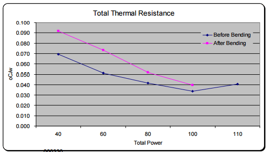
Figure 6: Total Thermal Resistance
Given that one should generally design a two-phase device to operate at 70% of its Qmax (we’ll use total power of 70W), we see that the thermal resistance of an un-bent device from 0.047 degrees c/w (3.3 °C) to 0.063 (4.4 °C) for a device with a U-shaped bend. This translates to a delta-T of only 0.9 degrees Celsius.
Based on this we can extrapolate some rules of thumb.
- Spec a straight heat pipe or vapor chamber with 30% thermal safety margin.
- Example: A lead load of 70w should use a heat pipe designed with a Qmax of no less than 91w.
- Add total bend radius of the heat pipe/VC. While not perfect this will get you very close to actual.
- Example: one 90 degree bend and another 45 degree bend = 135 degrees of bend
- For each 10 degrees of bend Qmax will decline by .56%.
- In our example from above: 135 degree total bend divided by 10 multiplied by 0.56% = 7.6% decrease in Qmax.
- So for our 70 w heat source with two bends totaling 135 degrees we’ll need a heat pipe with a Qmax of 70*(1+(.3+.076)) = 96.3w.

