Most thermal engineers are going to need a two-phase heat sink using either heat pipes or vapor chambers on numerous projects with which they are involved. Reasons include:
Keep out zones that prohibit a larger heat sink (thicker base, added fin area, etc.)
Enclosure size and/or airflow can’t be increased.
Transitioning to a solid copper heat sink, in whole or in part, adds too much weight and in some cases too much cost.
Component power /density necessitates heat be moved to a remote location more than 40-50mm away from the heat source.
In today’s blog we’d like to do a topline overview of structural differences and thermal design considerations between these very similar yet somewhat unique two-phase devices.If you need some background on the working principles of two-phase devices, please see our article “How do Heat Pipes Work”.
Structural Design & Cost
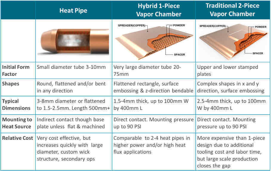
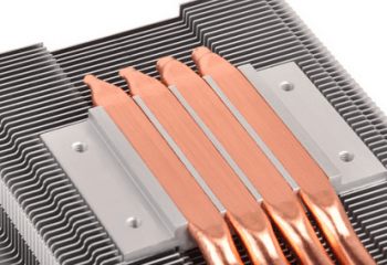
Heat pipes and vapor chambers are composed of the same materials. The most combination is a copper enclosure with a sintered copper wick material. The devices have a small amount of water added and are evacuated to create a partial vacuum. Vapor chambers have an additional support structure (spacer) added for structural integrity and to allow vapor to flow freely.
Unlike heat pipes, which have a width to height aspect ratio on the order of 4:1, vapor chambers can have aspect ratios of 60:1 or more. Additionally, vapor chambers can be divided into two categories:a traditional vapor chamber with two stamped plates forming the upper and lower enclosure and a lower cost hybrid 1-piece vapor chamber that begins the manufacturing process as a very large heat pipe.
Thermal Design Considerations
Heat Pipes
For decades, heat pipes have been the default two-phase device of choice for thermal engineers due largely to the cost deltarelative to vapor chambers. They were used both for heat transport, for which they still have an advantage, and for heat spreading, typically using multiple pipes near one another. For lower power applications, perhaps requiring only a single, small heat pipe, or those where heat must be effectively transported, heat pipes keep dominance over vapor chambers due to their low cost and design flexibility.
Heat Pipes Cooling Notebook Computer (Wikipedia)
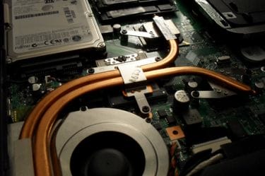
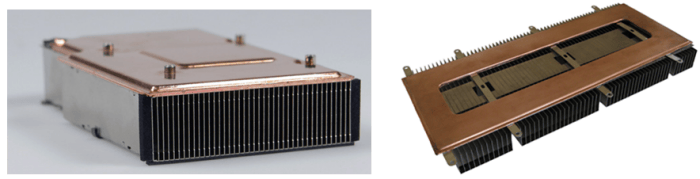
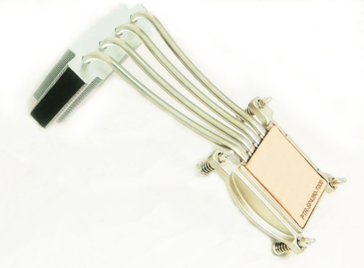
Greater total power and power densities eventually led to heat sinks using multiple heat pipes to solve the thermal challenge. Both images below are heat pipe heat sinks for a small form factor, high performance desktop PC. The one on the left uses a copper base plate in between the heat source and the heat pipes, as is common with heat pipe applications (indirect contact). As processor heat increased in the later generation of this product, the company encountered thermal issues, but did not want to radically redesign the thermal solution as can be seen on the image to the right. Here a vapor chamber replaced the copper base plate, spreading heat more evenly across the heat source and transferring it more effectively to the heat pipes. This is a notable example of how both types of two-phase devices can be used together.
Heat Pipe Heat Sink – (L) Using Solid Copper Baseplate, (R) Using Vapor Chamber (ixbtlabs.com & Celsia)
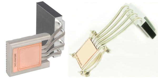
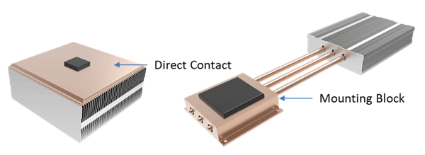
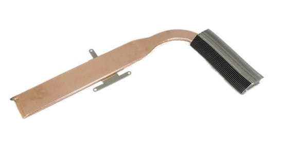
A potential alternative to this problem might have been to implement ‘direct contact’ heat pipes. But this solution has its drawbacks as well. As seen below, this design choice uses slightly flattened and machined heat pipes embedded in an aluminum mounting bracket to make direct contact with the heat source. While eliminating the base plate and addedTIM layer – decreasing thermal resistance – it doesn’t spread the heat as effectively as a vapor chamber heat sink solution.
Direct Contact Heat Pipes (Silverstonetek)
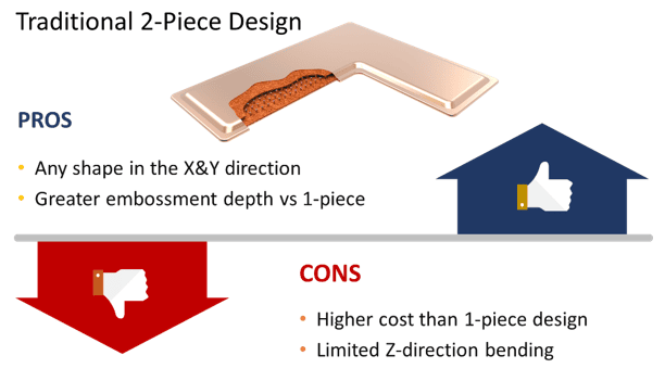
Traditional (2-Piece) Vapor Chamber
Most manufacturers of vapor chambers use a traditional two-piece design. Studies and practical applications show that the performance of heat sinks using vapor chambers can be enhanced by 20-30% over their heat pipe counterparts. A two-piece vapor chamber design has cost implications of roughly the same magnitude versus a multiple heat pipe configuration. Nonetheless, vapor chamber usage has grown with increasing total powers, higher power densities, and space constraints of today’s devices.
Because vapor chambers do an incredible job of spreading heat, allow for low-profile heat sinks, can be made into virtually any shape, embossed, and make direct contact with one or multiple heat sources, these devices are used in a wide variety of higher power applications. Below are two examples of heat sinks using two-piece vapor chambers.
Traditional Two-Piece Vapor Chamber (anandtech.com & Celsia)
As mentioned earlier, the increased cost of this design sometimes limits its incorporation into thermal solutions. Another potential drawback is that there’s little design flexibility in the z-direction. Making a U-shape for instance, while conceivably possible, would be impractical from a manufacturability/cost perspective.
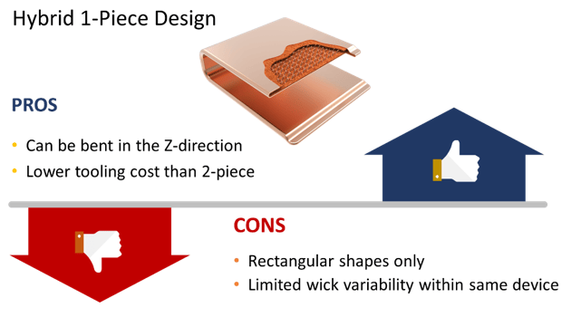
Hybrid (1-Piece) Vapor Chamber
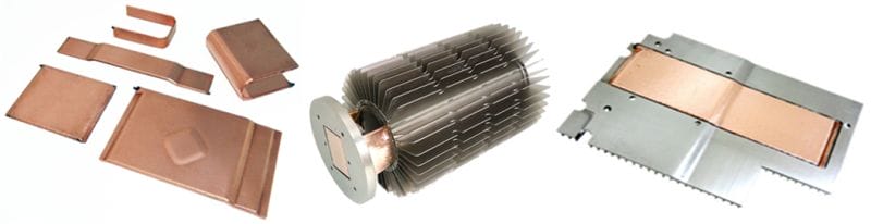
One-piece vapor chambers are a cost-reduced version of their two-piece counterparts yetkeep the thermal performance characteristics while adding some unique capabilities (e.g., U-shape bending). Like heat pipes, a one-piece vapor chamber begins its life as a single copper tube, hence the 1-piece moniker. Like traditional two-piece vapor chambers, one-piece vapor chambers make direct contact with the heat source, have a multi-directional heat flow, and can support clamping forces of up to 90 PSI. But they’re less expensive to produce because they need less tooling, don’t use individual support posts, and don’t have to be welded on all four sides. Below are a few examples of one-piece vapor chambers.
Hybrid One-Piece Vapor Chambers
The thing to remember about two-phase devices is that heat pipes favor moving heat over spreading it, while the reverse is true of vapor chambers. There are many thermal challenges where either could be used with satisfactory results so it’s important to do a thorough review process of both designs before settling on one.
Please contact us, if you’d like to learn more about how Celsia can help with your next heat sink project. We’ve worked on everything from consumer devices to industrial test equipment that require heat sinks to cool anywhere from a few watts to a few kilowatts.
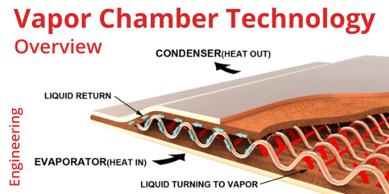
A vapor chamber is an effective heatpipe alternative that boosts heat sink performance by 5-10 oC for typical electronics cooling applications. Vapor chambers are a simple, relatively cost-effective, and very dependable device that can be used alone or in combination with heatpipes.
Vapor chambers operate under the same working principles as a heatpipe. They have a metal enclosure which is vacuum-sealed, an internal wick structure attached to the inside walls, and move liquid around the system using capillary action. Unlike heatpipes, vapor chambers can achieve an impressive 60:1 width to height aspect ratio (flattened heat pipes are on the order of 4:1).
Let’s take a look at the conditions most likely to result in vapor chambers becoming the best solution versus heatpipes or solid metal solutions.
Vapor Chambers When the Thermal Budget is Very Tight
Heatpipes become a likely solution when the thermal budget is less than 40 oC, but as this budget shrinks vapor chambers become the likely hero. The main reason? Vapor chambers make direct contact with the heat source while heatpipes generally have a base plate between them and the heat source.
Note: thermal budget is the difference between the maximum semiconductor temperature (Max Tcase or Tjunction) and the maximum operating ambient temperature of the final system (Max Ambient).
And yes, you are correct that a heat source can make direct contact with a heat pipe solution. Two issues:
The heatpipes have to be fly cut, adding an additional step and expense to the solution.
The mounting block still has solid metal channels between the pipes, reducing thermal performance and possibly creating die face hot spots.
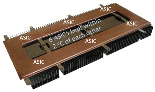
Vapor Chambers When You Need to “Isothermalize”
Vapor chambers are ideal for applications where high power densities need to be dispersed quickly, hot spots across the die face need to be minimized, or 2+ heat sources are required to be close in temperature. Below, 6 ASICS were required to remain within 2 oC of each other. The center cutout reduced weight.
When the goal is to achieve as uniform a temperature as possible, vapor chambers trump heatpipes by virtue of their large contiguous surface area that move heat in every direction. Heatpipes only move heat in a linear direction.
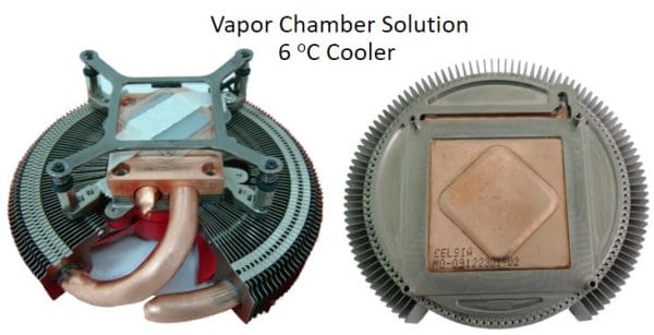
Vapor Chambers When Heat Sink Height is Constrained, Yet Fin Area Needs to Grow
Typically, heatpipes run through the center of a fin stack in order to maximize contact area and therefore transfer as much heat to the fins as possible. The downside – fin area is reduced. While this is not a problem if you’ve got the room to increase fin height, it poses a problem when that metric is constrained, as it is here in an add-in desktop graphics card application. A vapor chamber cooling design frees up needed fin area and provided direct contact to the heat source resulting in a 6 degree performance gain.
Vapor Chamber Conclusion
As mentioned in the opening to this article, heat sink performance improvement of 5-10 oC can be had by using a vapor chamber in place of heatpipes because they make direct contact with the heat source, can more evenly distribute heat across a large base, and allow for maximum fin area.
At Celsia, most of the applications for which we design benefit more from heatpipes than a vapor chamber, albeit those with application-driven changes to wick thickness and porosity to boost performance. But, that’s not to say we aren’t deeply invested in vapor chamber technology. The inherent performance benefits of these devices have been known since the 1960’s.
Vapor chamber cost relative to heat pipes, until a decade ago, was prohibitive for all but the most critical applications. Fortunately, the growing use of these devices coupled with innovative manufacturing techniques pioneered by us a decade ago (1-Piece Vapor Chamber) have driven the price down to near parity with 2-4 heat pipes. Below is a brief summary of the pros and cons of both types of vapor chambers, but more detail can be found here.
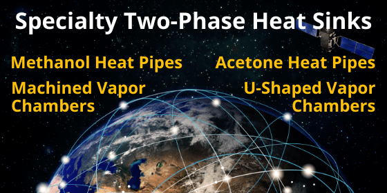
Heat pipe design is generally a straightforward process, but sometimes requirements can yield atypical heat pipe or vapor chamber designs, most notably methanol heat pipes, acetone heat pipes, and machined vapor chambers, in addition to a few interesting variations on standard designs.
Acetone & Methanol Heat Pipes
When operating temperature requirements are low and/or weight is a primary concern, acetone and methanol heat pipes can be alternatives to copper/water thermal solutions.
Above 0oC, standard heat pipes which use water as the working fluid operate normally: liquid turns to vapor which travels to the end of the device where the condenser cools it back to a liquid form that is transported via capillary action back to the evaporator. This process continues until the heat pipe suffers a structural failure or is heated to around 325 oC when vapor pressure is so high that there’s no liquid to be returned to the evaporator. Fortunately, heat pipes never reach those limits under normal operating conditions as most silicon chips start to fail at junction temperatures approaching 125 oC.
When heat pipes are required to operate below 0 oC, both acetone and methanol heat pipes eliminate the potential start-up issues with copper water heat pipes due to their freeze points being -48 oC and -75 oC respectively. As a general rule, engineers should consider methanol heat pipes before acetone ones as they will have a higher Qmax than their acetone counterparts. However, because methanol can only be used inside copper or stainless-steel enclosures / tubes while acetone can be used with aluminum, there is a weight penalty that might be important for applications such as space.
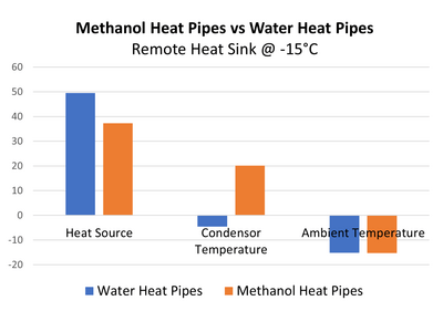
There are cases when it’s advantageous to use both methanol heat pipes and water heat pipes in the same heat sink design. The chart below shows just such an application. The methanol heat pipes eliminate any start-up issues below freezing (water heat pipes), allowing proper functioning of the condenser area of a remote heat sink when the temperature is -15 oC. Further, they allow the condenser area to heat above freezing, allowing the water heat pipes to fully function.
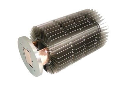
Machined Vapor Chamber Design
Not all applications needing two-phase devices can be adequately cooled with traditional heat pipe or vapor chamber solutions. This is where machined vapor chambers can be useful. Unlike traditional vapor chambers, these devices are machined to form complex shapes for all axes. The result is a device that can be attached to multiple heat sources on different planes, have other components affixed to them, and/or allow for unusually high clamping pressure without deforming while providing a tall stand-off to reach a recessed heat source.
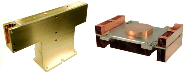
In high-performance test equipment, there are many unique challenges. The vapor chamber on the left allows for multiple parts to be fastened to it which is then liquid cooled at its base. This part is machined from solid copper incorporating two internal chambers that use sintered copper as the wick structure.
Machined Vapor Chamber Designs
A machined vapor chamber incorporated into the heat sink on the right allows features such as a pedestal that allows the machined vapor chamber to reach a recessed heat source. The pedestal is hollow and is part of the vapor chamber that moves the heat to the copper fins.
Variations on Standard 2-Phase Designs
Sometimes the usual heat pipe customization toolkit just is not enough to meet heat sink performance requirements. Here are some design alternatives that engineers might consider.
Combo Vapor Chamber / Heat Pipe Design
With two-phase devices, engineers typically choose either a vapor chamber design or a heat pipe design. In this instance, again because of design constraints, we needed both. This example is from a gaming oriented small form factor desktop using a higher end Intel processor. The customer wanted to move to the next generation with lower power but much lower max operating temperature (that means smaller thermal budget), without any radical change to the current thermal solution. As I’m sure you’ve guessed, it didn’t take a great leap of engineering acumen to suggest we replace the solid copper base plate with a vapor chamber (see our heat sink performance calculator).
Combo Vapor Chamber & Heat Pipe Heat Sink
Given heat pipes were already being used to move and distribute the heat to the condenser, we achieved a 4-6 degree C performance improvement from this solution. With a bit of fan speed tweaking from the system manufacturer, we were able to achieve the required performance targets.
Hybrid Heat Pipe & Vapor Chamber Design
As often happens, we were brought into the heat pipe design process after PCB and enclosure layout was finalized. Keep out zones were fixed, condenser size was adequate for the airflow, but the tentatively planned 6mm flattened heat pipe didn’t adequately cover or cool the CPU and GPU that were upstream from the condenser. Note – this picture only shows the one connector but there was another toward the end for the CPU.
Hybrid Heat Pipe (condenser end) and Vapor Chamber (evaporator end)
Given design constraints and performance requirements, a two-heat-pipe alternative was not an option nor was a larger flattened heat pipe. Swaging accomplished the two diameter tube prior to completing the heat pipe manufacturing process including the addition of an internal support structure providing the strength for the required clamping pressures.
Square Heat Pipe Design
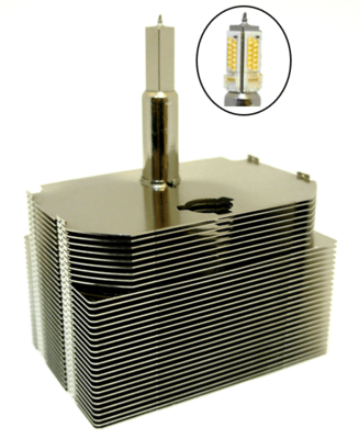
Heat pipes do not need to be round. In special applications square or rectangle cross sections provide the required interface to the electronics.
Square Heat Pipe Used for Theatrical LED Lighting Application
Due to optical issues, this heat pipe required 4 flat surfaces to which the LEDs are mounted. Additionally, it was required to work in any orientation. The design required a very specific wick structure in order to meet the targets. Initially, the design used a two-piece design, machined evaporator welded to a round tube. The second generation, cost reduced part is made from a single square tube.
U-Shape Vapor Chamber Design
Because vapor chambers are usually made from upper and lower stamped plates, they don’t lend themselves to shapes in the Z-direction. Over a decade ago, Celsia created a vapor chamber from a single very large tube, much like a heat pipe. The resulting width can be up to 110mm yet be as thin as 2.5mm. Of course, we add an internal support structure.
U-Shaped & Curved Vapor Chamber
The result is a vapor chamber that can be L or U-shaped yet still allowing for direct contact with the heat source. Although direct contact heat pipes are possible, they require machining which increases cost and they’re less effective at reducing hot spots on the die face. Additionally, the portion of the vapor chamber ‘legs’ that run along the inside of the condenser are slightly curved.
Bending Heat Pipes | How it Affects Vapor Chambers & Heat Pipes
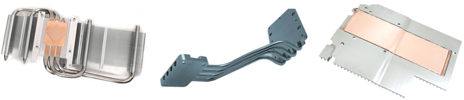
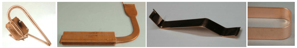
The majority of applications for heat pipes, and to a lesser extent vapor chambers, require these products to be bent. Below are respective examples for high-performance graphics card, semiconductor equipment and networking applications.
Figure 1: Heat Sinks Using Bent Two-Phase Devices
But what effect does bending a heat pipe or vapor chamber have on their performance? To answer this, let’s first talk about bend parameters then we’ll move into the meat of it and discuss both evaporator and vapor resistances.
Although smaller bend radii are possible, heat pipe guidelines almost universally put their c/l (centerline) bend radius at 3X the diameter of the heat pipe being bent. In other words, for a 5mm round heat pipe bent into a U shape, the resulting OD would be 35mm.
Bend radius for a 1.5-3.5mm thick vapor chambers are about 10mm. For instance, for a 2mm thick vapor chamber the OD of a 180 degree bend would be 22mm. While these would have to stamped into place for a traditional two-piece vapor chamber, one-piece designs can be bent post production, even into a U-shape.
Figure 2: Bending Examples
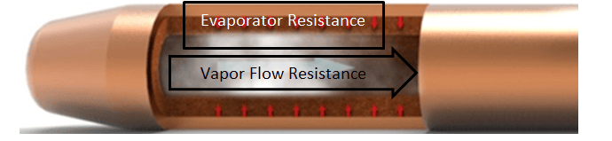
Two areas of thermal resistance in these devices must be closely examined. The first is evaporation resistance which is the deta-t due to conduction through the device wall and wick structure as well as phase change of the working fluid into vapor.
In the vast majority of applications, the evaporation resistance is the dominate resistance; therefore, making these devices somewhat length independent. This means that a two-phase device with a transport distance of 75 mm will have almost the same Tsource -Tsink as one with a 150 mm transport distance. This, in effect, doubles the effective thermal conductivity for the longer devices. For a typical water/copper heat pipe with 0.5mm wall and 0.4mm sintered wick, thermal resistance has a nominal value of about 0.1 oC/w/cm2
Figure 3: Heat Pipe
The second is vapor transport resistance which is the temperature loss in the transport region due to pressure drop and condensation delta-t’s. This resistance is typically a function of the power density in the vapor space – nominal power densities are 300-400 w/cm2 with a typical maximum of 800-1,000 w/cm2. The nominal thermal resistance of vapor transport is about 0.01o C/w/cm2. Because of the correlation between cross sectional area of the vapor space and vapor resistance, smaller diameter heat pipes or those that have been flattened increases vapor flow thermal resistance.
So how are these two key resistances affected by bending a two-phase device?
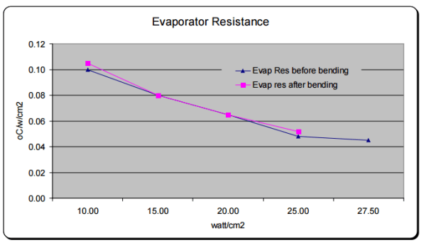
Because the evaporator is almost never placed at the arch of a bent two-phase device, we would expect relatively little to no increase in its nominal value when comparing straight and bend two-phase devices. When testing a 3mm thick U-shaped vapor chamber with a 10mm bend radius we see this to be true. Test data showing the evaporation resistance before and after bending is shown in Figure 4. The results are identical within measurement error.
Figure 4: Evaporator Resistance
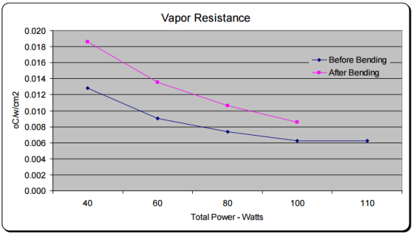
Now let’s look at vapor transport resistance. Due to the pressure drop induced by bending the vapor chamber, we would expect vapor transport resistance to increase due to an increase in pressure drop, thus decreasing the thermal conductivity of the device. Again, testing supports this claim and is relatively consistent between heat pipes and vapor chambers. Bending a two-phase device 180 degrees increases vapor flow resistance by around 50%.
Figure 5: Vapor Resistance
It’s important to note that while vapor transport resistance is significantly affected by bending, its relative contribution to overall thermal resistance is often small. Remember that for an un-bent part, evaporator resistance is a full order of magnitude greater than that of vapor flow resistance.
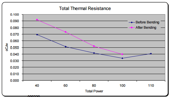
So, when we examine the overall thermal resistance, we see that the net effect is between 18-40%. You will also note a decrease in the total power. When relying on capillary pumping in the wick structure to return the fluid the bending affects the pore radius and porosity in the bend region. This has about a 10% effect on the Qmax post bending.
Figure 6: Total Thermal Resistance
Given that one should generally design a two-phase device to operate at 70% of its Qmax (we’ll use total power of 70W), we see that the thermal resistance of an un-bent device from 0.047 degrees c/w (3.3 °C) to 0.063 (4.4 °C) for a device with a U-shaped bend. This translates to a delta-T of only 0.9 degrees Celsius.
Based on this we can extrapolate some rules of thumb.
Spec a straight heat pipe or vapor chamber with 30% thermal safety margin.
Example: A lead load of 70w should use a heat pipe designed with a Qmax of no less than 91w.
Add total bend radius of the heat pipe/VC. While not perfect this will get you very close to actual.
Example: one 90 degree bend and another 45 degree bend = 135 degrees of bend
For each 10 degrees of bend Qmax will decline by .56%.
In our example from above: 135 degree total bend divided by 10 multiplied by 0.56% = 7.6% decrease in Qmax.
So for our 70 w heat source with two bends totaling 135 degrees we’ll need a heat pipe with a Qmax of 70*(1+(.3+.076)) = 96.3w.