This whitepaper considers heat sink design when developing thermal solutions for high heat flux electronics applications. Although there are design similarities with standard heat sinks, the focus will be on identifying the areas where differences emerge.
As will be shown, design decisions such as fin geometry and airflow are unaffected by changes in power density, all else being held constant. In other words, changing the die size of a 100W heat source from 35x35mm to 10x10mm will not alter design decisions that rely on convective heat transfer.
The primary challenge in high heat flux scenarios, typically characterized by power densities ranging from 50-500 W/cm2, lies in minimizing the thermal resistance caused by conduction. This paper covers the following topics:
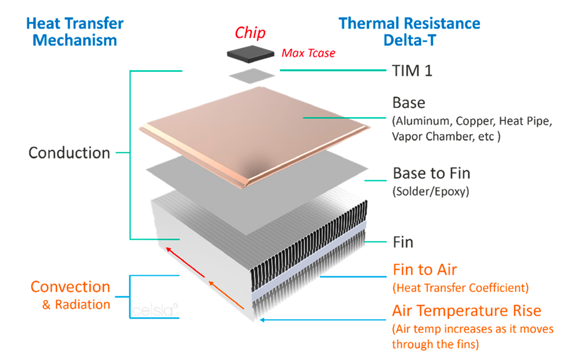
Diagram 1 shows a typical heat sink thermal resistance network, along with the corresponding heat transfer mechanism. Subtracting the maximum ambient operating temperature of the device (max Tambient) from the maximum allowable case temperature of the IC (max Tcase), yields the heat sink thermal budget. This figure represents the maximum allowable temperature rise of the heat sink (sum of TIM 1 down to Air Temp Rise) before the IC shuts down or throttles back power.
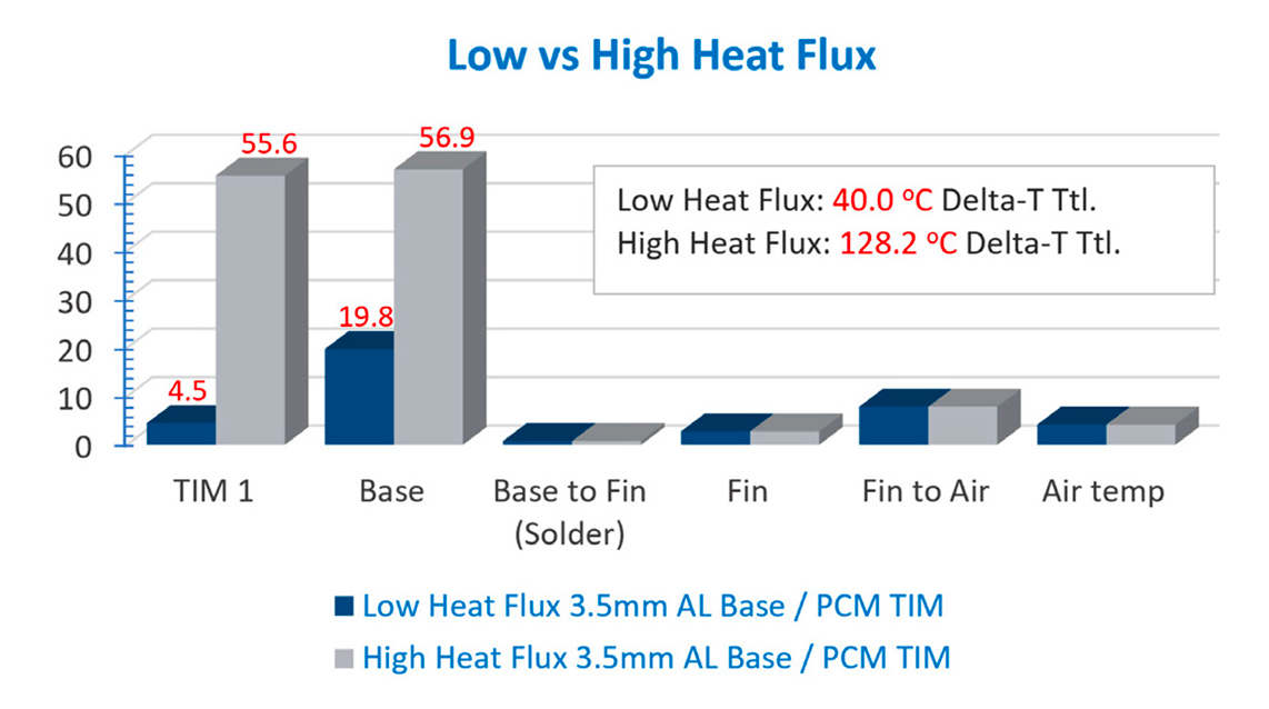
In this example, increasing heat flux from 8 to 100 W/cm2 has a big effect on the temperature rise of both the graphite based PCM (TIM1) and the 3.5mm aluminum heat sink base. The low heat flux scenario has a total heat sink temperature rise, delta-T, 5oC below the thermal budget of 45oC. After the die size is reduced, delta-T is 83oC over budget.
By holding constant all variables except heat source size, the challenge of high power density applications becomes glaringly apparent.
Assume:
Chart 1 compares the delta-T for each element of the resistance network when the heat source is changed from 35x35mm to 10x10mm.
Diagram 1: Heat Sink Thermal Resistance Breakdown by Heat Transfer Type
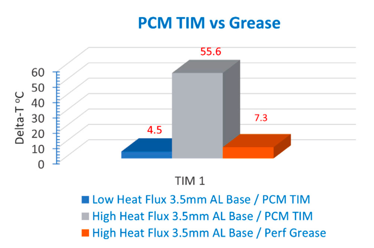

With the temperature rise due to TIM material largely solved, the next step is reducing the thermal resistance in the base of the heat sink which currently drives a 56.9oC delta-T. The most common methods used to achieve this goal are substituting copper for aluminum, increasing the thickness of the base, and transitioning to a two-phase device such as heat pipes or vapor chambers.
Because copper has roughly twice the thermal conductivity of aluminum, swapping a heat sink base of the same size halves the temperature rise in the base, as seen in Chart 3.
When switching from aluminum to copper with a thickness of 3.5mm, the temperature rise in the base significantly decreases from nearly 57°C to just over 27°C. However, despite achieving a new total heat sink delta-T of 50.4°C, the combination of copper and grease solution still exceeds the target thermal budget by over 5°C.
It is critical for engineers to carefully assess whether the potential benefits of further optimization can offset the weight and cost penalties associated with this solution.
Copper Weight Penalty: Copper has twice the thermal conductivity and three times the density of aluminum. The added weight may cause concern for aeronautical applications and scenarios where elevated levels of shock and vibrations are encountered. This problem will be compounded for extruded or skived heat sinks where the base and the fins are made from the same material. In these situations, both the base and the fin stack will be copper.
Copper Cost Penalty: Although the difference varies over time, the price of copper is twice that of aluminum. Factoring in the added weight per unit of volume, this makes copper six times more expensive.
Unlike thermal interface materials, the thermal resistance of solid metal used in a heat sink base and fins decreases as it’s made thicker. In a base application, increasing the metal thickness increases the cross sectional area for the heat to travel while increasing the thickness of a TIM increases the distance the heat must travel.
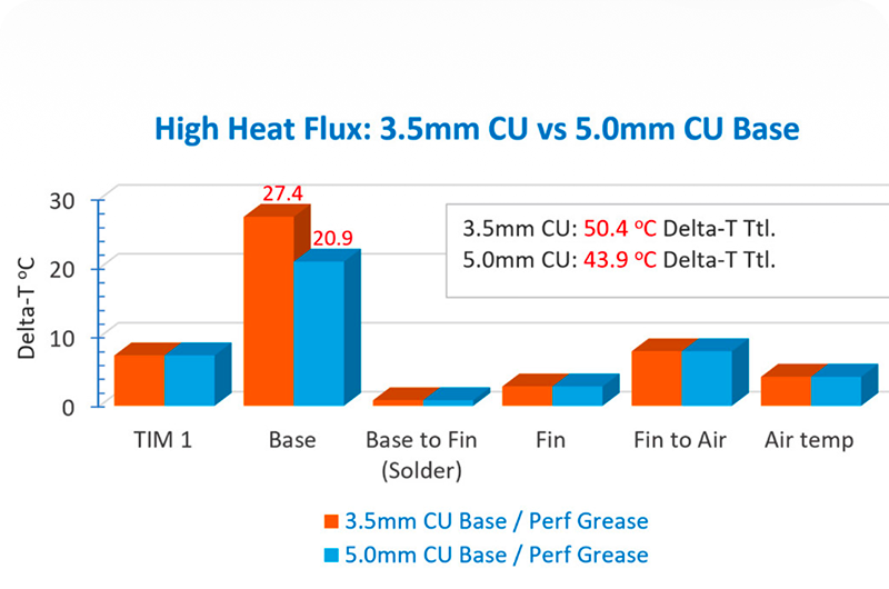
As seen in Chart 4 (see next page), increasing the copper base thickness from 3.5 to 5.0mm results in a total heat sink delta-T just below the max thermal budget of 45oC. Of course, this improvement comes with additional weight and cost penalties.
Alone or embedded within an aluminum or copper base, two-phase devices can improve thermal performance, keep weight down, and potentially save cost. This is especially true for high heat flux applications where efficiently moving or spreading the heat is crucial.
Unlike solid metal solutions, heat pipes or vapor chambers do not have a constant thermal conductivity as this figure increases with the distance heat is transported. As a general rule, consider using a twophase device when heat needs to be moved more than 50mm from the heat source edge and/or if the area over which the heat needs to be spread is more than ten times the area of the heat source.
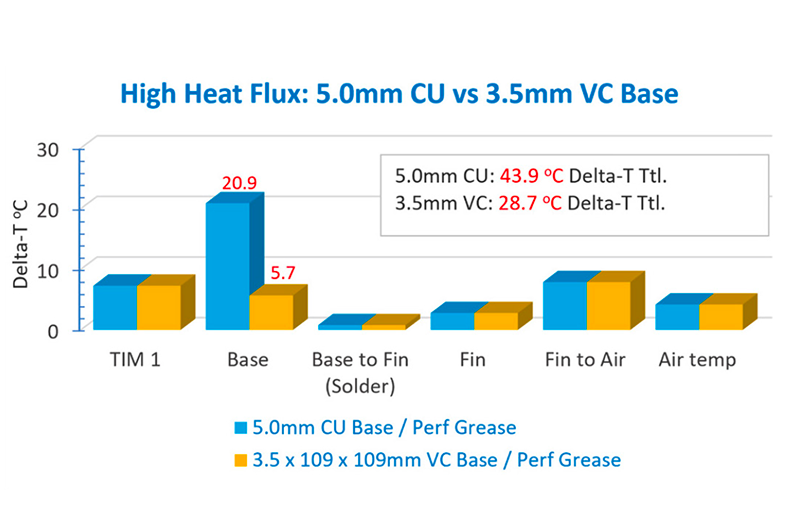
Chart 5 shows the vapor chamber solution reducing the delta-T in the base by over 15oC. The 5.7oC temperature rise is also well below the original “low heat flux” scenario.
Once the general design approach is determined, performance and cost optimization can be performed in CFD and later validated through prototype testing. As seen above, the vapor chamber solution yields a heat sink with a total delta-T of 28.7oC, considerably below our thermal budget of 45oC. Assuming cost and weight considerations are more important than excess thermal headroom, the next step might be to reduce the dimensions of the heat sink.
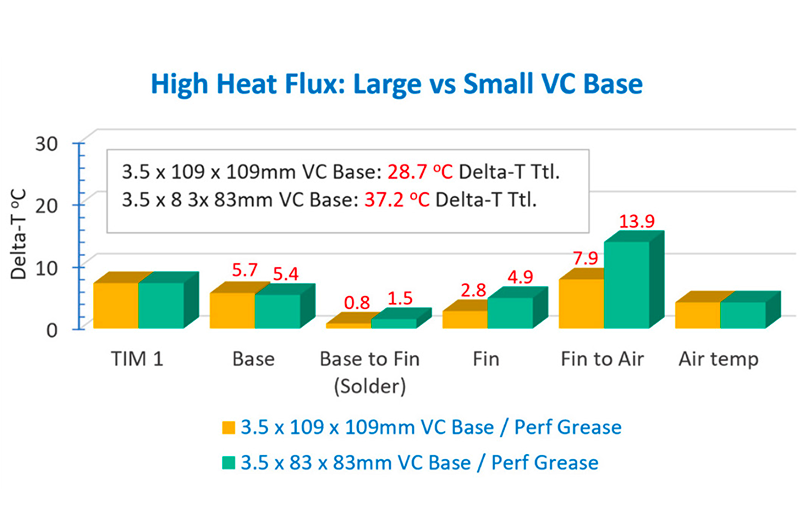
From Chart 6, reducing the base from 109x109mm to 83x83mm increases the overall delta-T of the solution to 37.2oC, still nearly 8 degrees below the thermal budget but with reduced weight and cost.
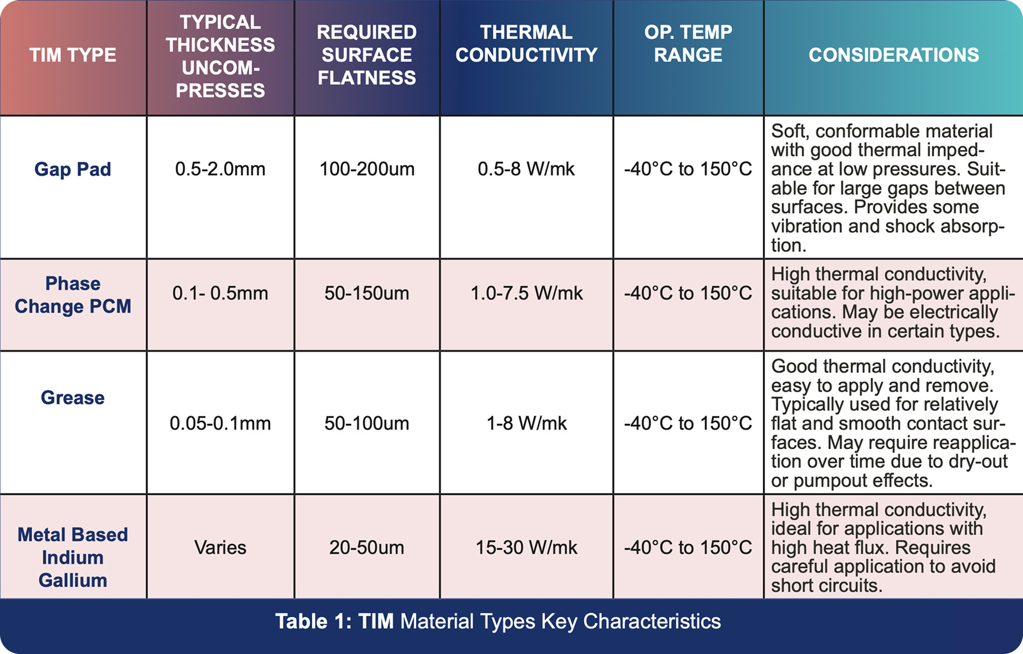
In summary, it is vital to focus on the main obstacle in high heat flux applications, which centers on the reduction of temperature increase due to conduction in the heat sink. Choosing the right thermal interface material, considering its type and thickness, is instrumental in overcoming this obstacle. Equally important is the choice of base material. Several common choices include aluminum, copper, and two-phase devices such as heat pipes or vapor chambers.
The final choices are subject to the various design parameters and trade offs, encompassing thermal performance, maintenance, cost, weight, and size considerations. Once the general heat sink design direction is determined, performance validation and optimization through CFD modeling and prototype testing are the final steps.