Recently, oscillating heat pipes (OHPs), also referred to as pulsating heat pipes, have piqued the interest of the thermal community. Despite research going back over three decades, there’s still a good deal of misunderstanding and a bit of hyperbole surrounding this two-phase cooling technology.
The goals of this whitepaper are to clearly define OHPs, discuss differences with traditional types of heat pipes, highlight the advantages and disadvantages of the technology, and provide a broad overview of design considerations.
An oscillating heat pipe is a two-phase thermal device used to efficiently move heat over fairly long distances while remaining small in size and more capable in different orientations than traditional heat pipes: wicked heat pipes, wicked vapor chambers, and looped heat pipes.
Physically, OHPs are comprised of a continuous usually serpentine design that can be con¿gured in shapes that closely match the available space in the end device. Each path within the shape is narrow, on the order of 1-3mm in diameter, to allow the surface tension of the working Àuid to form a series of liquid ‘slugs’ and vapor bubbles inside the partially evacuated device.
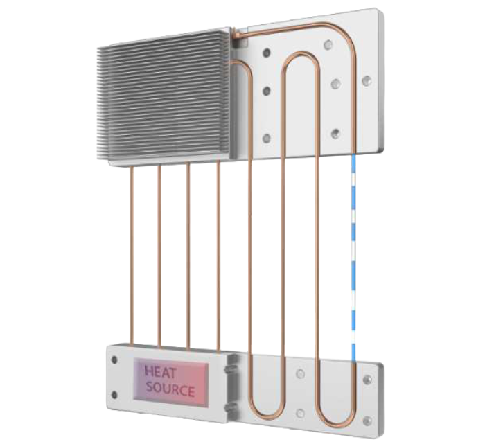
Figure 1 – Continuous Loop OHP:
Alternating Liquid Slugs & Vapor Bubbles
Oscillating and traditional heat pipes offer the same working fluid flexibility: water, alcohols, and refrigerants can all be used. However, this choice is closely linked with achieving optimal performance within the intended operating temperature range. Equally significant are the dimensions of the heat pipe, its size, and the orientation in which the device is designed to operate.
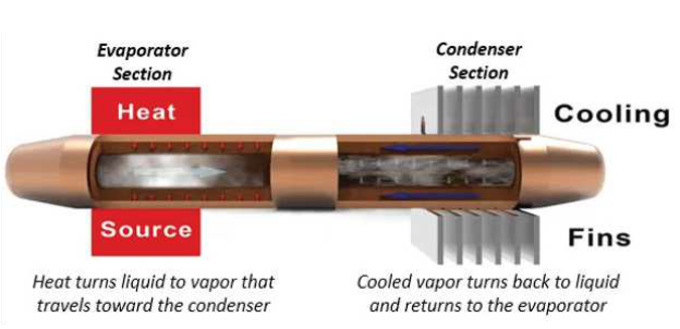
Operationally, OHPs work like this:
There are a couple of traditional types of heat pipes that warrant a summary as they are the ones most likely to face design competition from oscillating heat pipes.
Grooved, mesh, braided, and sintered wicks are used to transport liquid from the condenser (heat sink) back to the heat source (evaporator). These wick types are ordered from the least to most capable of operation (liquid transport) against gravity when the evaporator is above the condenser.
With these devices, vaporized liquid is responsible for nearly all the heat transfer with a small amount coming from conduction along the pipe’s metal wall.
As the power carrying capacity (Qmax) requirements increase, designers choose either a larger diameter tube or several smaller diameter tubes. These typically range from 2-10mm in diameter and can carry liquid fully against gravity to a height of around 150mm.
Further, the type and thickness of the internal wick structure, while necessary for Àuid transport, take away vapor space lessening its heat transport capacity. This means that a 2mm OHP can carry more heat than a 2mm wicked heat pipe. All of these working principles and attributes also apply to a heat pipe’s closest cousin, a vapor chamber.
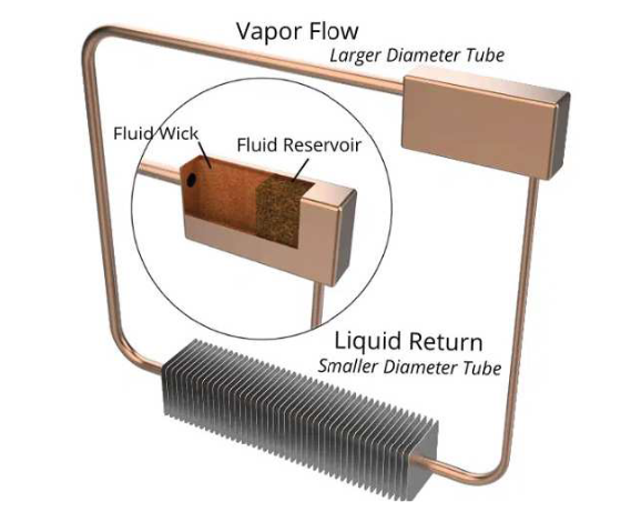
A loop heat pipe is similar to an OHP in several ways. First, it is a continuous, interconnected system. Second, the tubes contain no wick structure to maximize heat transport capacity only the hollow base plate that interfaces with the heat source has a wick. Third, it works against gravity by using vapor pressure to drive the liquid to lower-pressure areas.
Its operation depends on the ability of the working fluid to achieve high enough vapor pressure when heated to push the liquid condensate back to the evaporator section of the device. Unfortunately, this can’t usually be done with water as the working fluid. Instead, loop heat pipes use a refrigerant like ammonia where high pressure can be achieved at typical operating temperatures of electronics. Generally, we see this type of device in space-related applications.
While the conceptual design and early research into OHPs dates back a few decades, the full capabilities, characterization, and mass production efficiencies of these devices are substantially different from those of traditional heat pipes. Consequently, the degree of OHP advantage and to some extent the type of advantage has changed over time. The following benefits are what we at Celsia believe to be the most likely pegs on which to hang the laurels of oscillating heat pipes:
For most applications, heat transfer in electronics cooling is generally less than 300mm. Traditional heat pipes work efficiently up to a meter in a horizontal position but need to be shortened substantially if the evaporator is directly above the condenser. For longer distances, looped designs were historically preferred for applications up to around 2 meters, but anything beyond that required active cooling systems. OHPs, on the other hand, can cover several meters or more due to their vapor pressure-based circulation, making them ideal for applications like spacecraft thermal management.
Oscillating heat pipes facilitate effective heat transfer, even in intricate configurations. Their design accommodates multiple turns and bends without compromising efficiency, offering engineers greater design choices than traditional heat pipes. OHPs can be integrated directly into a solution by machining grooves into the metal thermal plane. Notably, their Qmax per cross-sectional area surpasses that of standard heat pipes, which are capillary limited. This compactness leads to thermal solutions that are slimmer and lighter, making OHPs a promising choice for aeronautical or wearable electronic applications.
Both standard and oscillating heat pipes can function in orientations opposing gravity. However, oscillating heat pipes, which aren’t dependent on capillary
action, generally outperform standard ones in smaller tubes (about 1-3 mm, depending on the fluid). While a standard heat pipe operates effectively up to approximately 150mm against gravity, an OHP can extend its efficiency to about 1-1.5 meters. Additionally, an OHP’s Qmax declines more gradually compared to standard heat pipes when transitioning from horizontal to opposing gravity.
Oscillating heat pipes have just begun to reach the acceptance and commercialization phase of market penetration, albeit largely for military and space applications. Design engineers considering this technology should be aware of some general design guidelines when choosing this path.
OHPs need a specific pressure differential to function. This leads to a slower start-up, which could pose thermal concerns in the initial phase. It’s essential to conduct tests and analyses to ensure components stay below their temperature limits during this time. Bare die devices, with their minimal thermal mass,
may be particularly vulnerable. However, this start-up instability typically arises at lower temperatures, where there’s a more lenient thermal margin. For most applications, this isn’t a significant concern especially when fluids with higher vapor pressure, such as methanol, are used.
Oscillating Heat Pipes (OHPs) exhibit comparable heat flux capabilities to those of high-performance heat pipes. However, they possess a distinct advantage: the capacity to transport larger quantities of heat. This disparity in capabilities arises due to the underlying operational principles. While high-performance heat pipes (HPs) are constrained by capillary action, OHPs function as pumped systems, leveraging vapor propulsion to facilitate fluid distribution throughout the system.
One notable aspect of OHPs is their exceptional capability to manage heat flux. These systems are adept at handling heat fluxes reaching hundreds of
watts per square centimeter. This remarkable attribute underscores the potency of OHPs in effectively managing substantial thermal loads. By enabling
efficient heat transport and distribution, OHPs provide an innovative solution in scenarios requiring robust thermal management performance.
OHPs perform optimally with a heightened pressure differential inside the tube between the evaporator and condenser sections. The efficiency of OHPs intensifies as this pressure differential grows. Efficient heat extraction caused by improved (active) condenser efficiency leads to a larger pressure difference,
which in turn boosts fluid and vapor circulation in the system. Essentially, the more effective the cooling, the more enhanced the OHP performance becomes.
Incorporating forced convection plays a pivotal role in harnessing the inherent advantages of OHPs. By facilitating temperature disparities, forced convection
empowers OHPs to enhance their operational efficiency.
When comparing heat pipes and vapor chambers in terms of shock and vibration resistance, a key distinction emerges. Oscillating heat pipes offer a unique advantage by seamlessly integrating into the thermal plane, as opposed to being an independent component that’s attached separately. This integration effectively eradicates the possibility of delamination and voids at the joint, thereby reducing the impact of thermal interfaces. The result is a sturdier assembly that’s better equipped to withstand shocks and vibrations, enhancing overall reliability. Further, because grooves are machined or etched into an existing structure, this manufacturing approach creates the thinnest OHP design.
However, if the more common tube design is incorporated, each tube (like a traditional heat pipe) can be soldered to the thermal plane. Further shock and vibration enhancements can include clamping the structure.
Oscillating heat pipes are emerging as a viable option in thermal management, especially when space is limited, heat needs to be transported over longer distances, or when the heat sink operates against gravity. Though still in the early stages of commercialization and characterization, the initial results are promising. OHPs display similar Qmax and heat flux capabilities as traditional heat pipes, but potential startup issues warrant careful design considerations. Enhancing airflow has been identified as a means to boost OHP performance, underscoring the importance of integrated design approaches.
In essence, OHPs offer a new avenue in thermal management solutions. As with any newer technology, continued research and testing will be essential to harness their full
potential.