Methanol Heat Pipes, Acetone Heat Pipes, & Machined Vapor Chambers
Heat pipe design is generally a straightforward process, but sometimes requirements can yield atypical heat pipe or vapor chamber designs, most notably methanol heat pipes, acetone heat pipes, and machined vapor chambers, in addition to a few interesting variations on standard designs.
Acetone & Methanol Heat Pipes
When operating temperature requirements are low and/or weight is a primary concern, acetone and methanol heat pipes can be alternatives to copper/water thermal solutions.
Above 0oC, standard heat pipes which use water as the working fluid operate normally: liquid turns to vapor which travels to the end of the device where the condenser cools it back to a liquid form that is transported via capillary action back to the evaporator. This process continues until the heat pipe suffers a structural failure or is heated to around 325 oC when vapor pressure is so high that there’s no liquid to be returned to the evaporator. Fortunately, heat pipes never reach those limits under normal operating conditions as most silicon chips start to fail at junction temperatures approaching 125 oC.
When heat pipes are required to operate below 0 oC, both acetone and methanol heat pipes eliminate the potential start-up issues with copper water heat pipes due to their freeze points being -48 oC and -75 oC respectively. As a general rule, engineers should consider methanol heat pipes before acetone ones as they will have a higher Qmax than their acetone counterparts. However, because methanol can only be used inside copper or stainless-steel enclosures / tubes while acetone can be used with aluminum, there is a weight penalty that might be important for applications such as space.
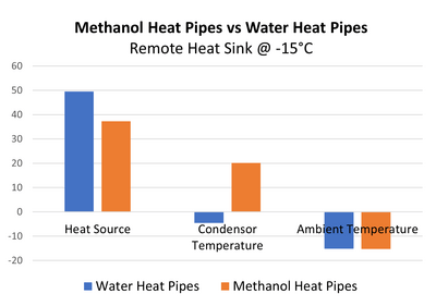
There are cases when it’s advantageous to use both methanol heat pipes and water heat pipes in the same heat sink design. The chart below shows just such an application. The methanol heat pipes eliminate any start-up issues below freezing (water heat pipes), allowing proper functioning of the condenser area of a remote heat sink when the temperature is -15 oC. Further, they allow the condenser area to heat above freezing, allowing the water heat pipes to fully function.
Machined Vapor Chamber Design
Not all applications needing two-phase devices can be adequately cooled with traditional heat pipe or vapor chamber solutions. This is where machined vapor chambers can be useful. Unlike traditional vapor chambers, these devices are machined to form complex shapes for all axes. The result is a device that can be attached to multiple heat sources on different planes, have other components affixed to them, and/or allow for unusually high clamping pressure without deforming while providing a tall stand-off to reach a recessed heat source.
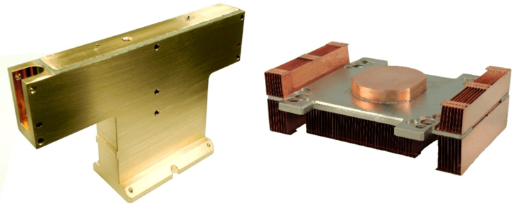
In high-performance test equipment, there are many unique challenges. The vapor chamber on the left allows for multiple parts to be fastened to it which is then liquid cooled at its base. This part is machined from solid copper incorporating two internal chambers that use sintered copper as the wick structure.
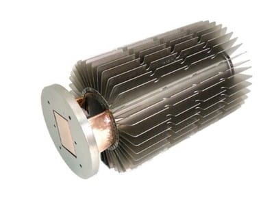
Machined Vapor Chamber Designs
A machined vapor chamber incorporated into the heat sink on the right allows features such as a pedestal that allows the machined vapor chamber to reach a recessed heat source. The pedestal is hollow and is part of the vapor chamber that moves the heat to the copper fins.
Variations on Standard 2-Phase Designs
Sometimes the usual heat pipe customization toolkit just is not enough to meet heat sink performance requirements. Here are some design alternatives that engineers might consider.
Combo Vapor Chamber / Heat Pipe Design
With two-phase devices, engineers typically choose either a vapor chamber design or a heat pipe design. In this instance, again because of design constraints, we needed both. This example is from a gaming oriented small form factor desktop using a higher end Intel processor. The customer wanted to move to the next generation with lower power but much lower max operating temperature (that means smaller thermal budget), without any radical change to the current thermal solution. As I’m sure you’ve guessed, it didn’t take a great leap of engineering acumen to suggest we replace the solid copper base plate with a vapor chamber (see our heat sink performance calculator).
Combo Vapor Chamber & Heat Pipe Heat Sink
Given heat pipes were already being used to move and distribute the heat to the condenser, we achieved a 4-6 degree C performance improvement from this solution. With a bit of fan speed tweaking from the system manufacturer, we were able to achieve the required performance targets.
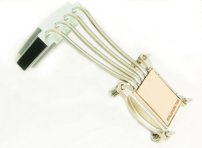
Hybrid Heat Pipe & Vapor Chamber Design
As often happens, we were brought into the heat pipe design process after PCB and enclosure layout was finalized. Keep out zones were fixed, condenser size was adequate for the airflow, but the tentatively planned 6mm flattened heat pipe didn’t adequately cover or cool the CPU and GPU that were upstream from the condenser. Note – this picture only shows the one connector but there was another toward the end for the CPU.
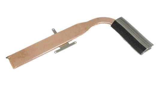
Hybrid Heat Pipe (condenser end) and Vapor Chamber (evaporator end)
Given design constraints and performance requirements, a two-heat-pipe alternative was not an option nor was a larger flattened heat pipe. Swaging accomplished the two diameter tube prior to completing the heat pipe manufacturing process including the addition of an internal support structure providing the strength for the required clamping pressures.
Square Heat Pipe Design
Heat pipes do not need to be round. In special applications square or rectangle cross sections provide the required interface to the electronics.
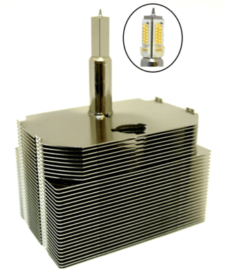
Square Heat Pipe Used for Theatrical LED Lighting Application
Due to optical issues, this heat pipe required 4 flat surfaces to which the LEDs are mounted. Additionally, it was required to work in any orientation. The design required a very specific wick structure in order to meet the targets. Initially, the design used a two-piece design, machined evaporator welded to a round tube. The second generation, cost reduced part is made from a single square tube.
U-Shape Vapor Chamber Design
Because vapor chambers are usually made from upper and lower stamped plates, they don’t lend themselves to shapes in the Z-direction. Over a decade ago, Celsia created a vapor chamber from a single very large tube, much like a heat pipe. The resulting width can be up to 110mm yet be as thin as 2.5mm. Of course, we add an internal support structure.
U-Shaped & Curved Vapor Chamber
The result is a vapor chamber that can be L or U-shaped yet still allowing for direct contact with the heat source. Although direct contact heat pipes are possible, they require machining which increases cost and they’re less effective at reducing hot spots on the die face. Additionally, the portion of the vapor chamber ‘legs’ that run along the inside of the condenser are slightly curved.