Industries / Aerospace

Aerospace Thermal Management

Traceable, qualification-ready thermal solutions for flight environments.
Celsia develops custom aerospace thermal management solutions for power-dense electronics operating within tightly constrained mechanical and environmental envelopes. Using heat pipes, vapor chambers, thermosyphons, and integrated thermal assemblies, we help aerospace engineering teams optimize thermal paths, reduce spreading resistance, and maintain reliability without adding significant mass or power consumption.
Qualified & Compliant
Validated to MIL-STD-810
Critical role

Critical role of aerospace thermal management in high-reliability electronics.

Localized device heat flux

50–100 W/cm²

Commonly exceeded in modern aerospace electronics — the regime where conventional solid conduction paths can no longer be packaged within constrained mechanical envelopes.
As aerospace electronics become more power-dense, localized device heat flux commonly exceeds 50–100 W/cm², increasing spreading resistance and making conventional solid conduction paths difficult to package within constrained mechanical envelopes. As power density increases across avionics, radar, RF systems, onboard processing, and power electronics, thermal management becomes a system-level design constraint rather than a component-level consideration.
Why two-phase design

Higher effective conductivity, same mechanical envelope.

FIG. 01 — Solid conduction vs. phase-change heat spreading. A solid metal plate moves heat by conduction alone — slower lateral spread, higher hot-spot. A vapor chamber spreads heat by vaporization and condensation for rapid, uniform distribution within the same envelope.
Two-phase thermal solutions are commonly applied where conduction path length, packaging geometry, allowable mass, or available cooling capacity limit the effectiveness of conventional solid metal spreaders.

By transporting and spreading heat with significantly higher effective thermal conductivity, two-phase cooling technologies reduce thermal resistance and help maintain lower source-to-sink ΔT within constrained mechanical envelopes — without adding active cooling power or excessive structural mass.

Heat pipes and vapor chambers are commonly integrated into chassis, cold plates, conduction-cooled assemblies, and other high-power aerospace electronics where stable thermal performance must be maintained across varying environmental and operating conditions.
Environmental envelope

Conditions driving design selection.

Most aerospace programs stack three or more of these conditions. The right thermal path is the one that holds across the whole envelope, not the average case.
Extreme cold soak to elevated temperatures

Operating range from deep cold-soak conditions to elevated internal enclosure temperatures.

High vibration & mechanical shock

Launch, sustained flight, and platform-specific shock and vibration spectra.

Reduced airflow / sealed enclosures

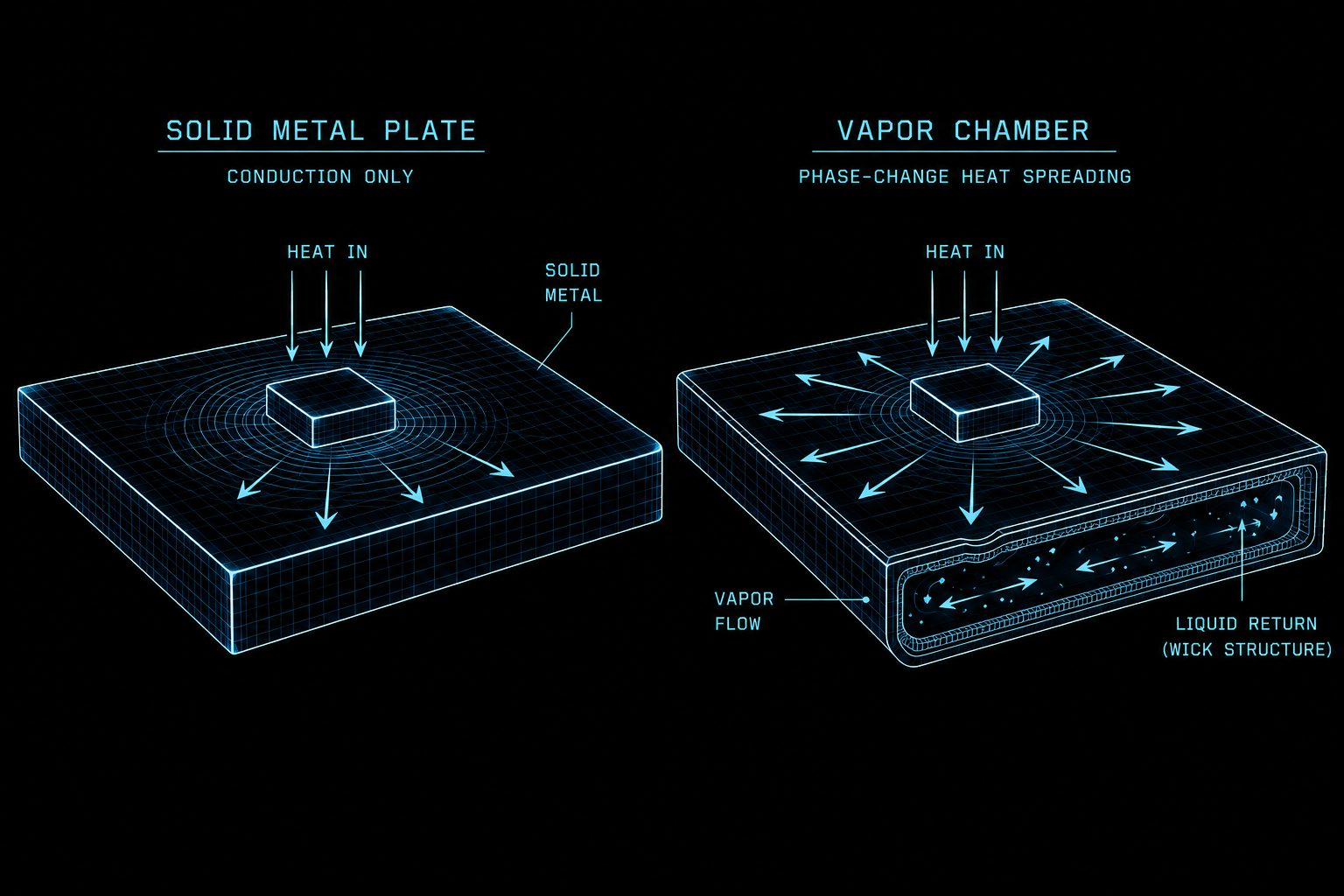
Conduction-cooled and hermetically sealed assemblies — every watt exits through the wall.

Aggressive SWaP

Size, weight, and power budgets that exclude bulky air-moving solutions.

Thermal cycling over long lifetimes

Repeated hot-cold transitions across orbital sun/eclipse cycles and mission profiles.

High heat flux from compact electronics

Concentrated dissipation from compact processing, RF devices, and power amplifiers.

Long-duration reliability

Multi-year operation without working-fluid loss, wick degradation, or seal failure.

MIL-STD qualification

Environmental and qualification test stacks scoped to the platform's mission profile.

Where does your program land in this envelope?
Applications

Aerospace thermal management applications.

Celsia’s thermal management solutions support aerospace electronics operating across airborne platforms, orbital systems, and other high-reliability applications where thermal performance, mass efficiency, and long-duration reliability must be maintained under demanding environmental conditions.
Airborne platform
Application 01

Airborne Platforms

Thermal management for avionics, radar systems, RF electronics, embedded computing, and power electronics operating within compact, vibration-prone, and airflow-constrained aerospace environments.
Avionics
Radar
RF
Embedded Computing
Power Electronics
On-orbit satellite
Application 02

Orbital & Satellite Systems

Passive thermal solutions for satellite electronics, payload processing, RF systems, optical electronics, and power conditioning assemblies where efficient heat transport, reduced mass, and long-term reliability are critical.
Satellite Electronics
Payload Processing
RF
Optical
Power Conditioning
Custom thermal solutions

Custom thermal solutions for aerospace.

We develop integrated aerospace thermal management architectures for electronics systems where conduction path limitations, heat flux density, mechanical constraints, and qualification requirements must be balanced across the complete thermal path.

Using heat pipes, vapor chambers, thermosiphons, thermal straps, and integrated heat sinks, every solution is engineered around the application’s thermal envelope, packaging constraints, environmental conditions, and long-term reliability requirements — from technology selection through system-level design and validation.
Two-phase assembly
TECHNOLOGIES WE DESIGN WITH

Proven technologies for challenging thermal requirements.

Each technology is selected and tuned to the application — then integrated into a single qualified assembly. Each links to a design page with selection criteria and performance envelopes.

Heat pipes

Heat pipes transport heat from board-level dissipators to chassis sidewalls, cold plates, or remote heat rejection interfaces. Sintered wick structures are selected based on orientation, thermal load, and environmental requirements.

Vapor chambers

Vapor chambers reduce in-plane thermal resistance and improve temperature uniformity compared to equivalent solid metal spreaders within the same envelope.

Thermosiphon

Thermosiphons handle high-capacity passive heat transport where gravity-assisted condensate return moves heat over longer distances with minimal thermal resistance.

Thermal strap

Thermal straps provide mechanically flexible coupling between heat-generating components and remote cooling structures where vibration isolation, thermal expansion, or mechanical decoupling are required.
Synthesis

Integrated thermal assemblies

Integrated thermal assemblies combine heat pipes, vapor chambers, thermal straps, and heat sinks into complete thermal management solutions — optimized for the application’s thermal load, mechanical constraints, environmental conditions, and qualification requirements.
Technology selection

Matching the technology to the challenge.

A starting point — not a substitute for analysis. Most aerospace programs stack several of these conditions, and the right path is the one that holds across the whole envelope.
Challenge Vapor Chamber Heat Pipe Thermosiphon
High heat flux ✓✓✓
Long transport distance ✓✓✓ ✓✓
Gravity assisted ✓✓✓
Thin package ✓✓✓
Large spreading area ✓✓✓

✓✓✓ strong fit  ·  ✓✓ capable  ·  possible  ·  not suited

System-level design

Engineered around the boundary conditions.

Component selection is the easy part. Two-phase systems live or die on the boundary conditions — how heat enters the wick, how it leaves the condenser, how the assembly survives years of cycling without changing. These are the variables our engineers model and verify on every aerospace program.
Working fluid & envelope

Fluid and envelope material matched to the operating window: water with copper for room-temperature ranges, methanol or alternates where cold-side excursions exceed water's freeze tolerance.

Wick architecture

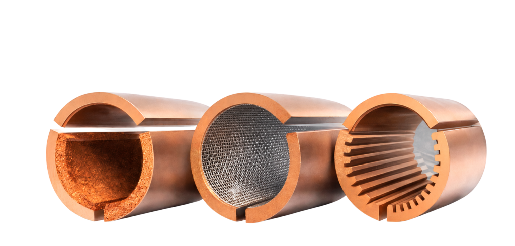
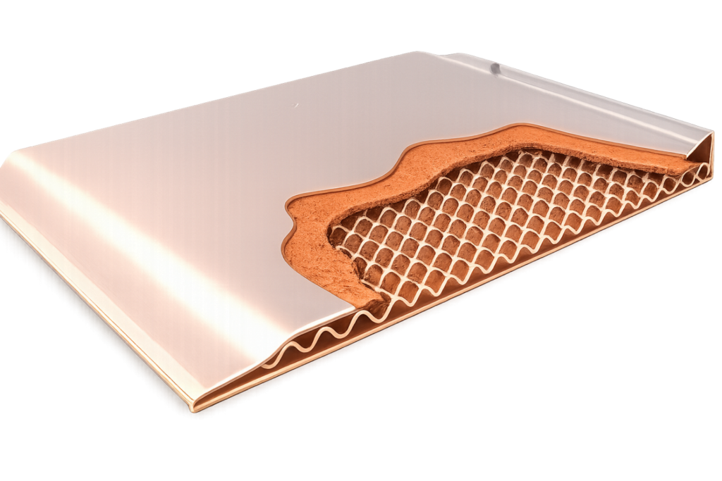
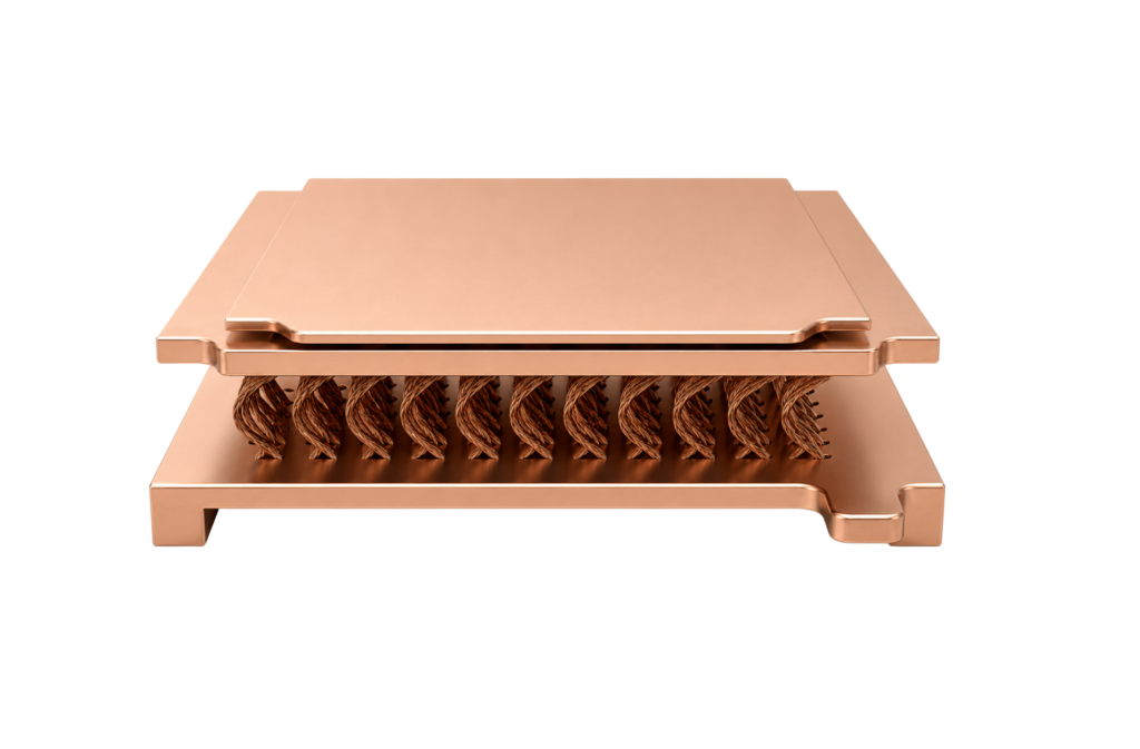
Sintered, screen, or grooved wicks selected for the orientation, acceleration, and environmental cycling requirements — not for cost.

Qmax & capillary performance

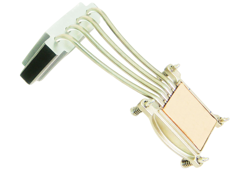
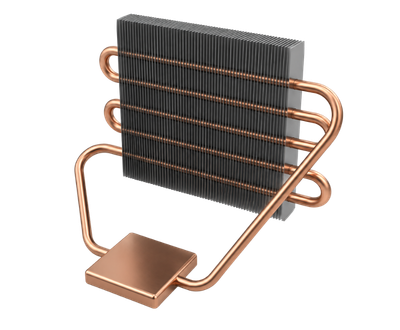
Heat pipe Qmax and capillary performance evaluated against the application's orientation and load profile.

Phase-change materials

Applied where transient or cyclic heat loads benefit from latent-heat buffering.

Heat sink fin geometry

Fin geometry sized for the rejection environment of the application — airflow, radiator coupling, pressure drop.

Thermal interface materials

Selected for stable resistance through thermal cycling and compatibility with the operating environment.

From technology selection through a qualified, manufacturable assembly.
System-level design

Engineered around the boundary conditions.

Component selection is the easy part. Two-phase systems live or die on the boundary conditions — how heat enters the wick, how it leaves the condenser, how the assembly survives years of cycling without changing. These are the variables our engineers model and verify on every aerospace program.

Hermetic seals & pressure margin

Hermetic seals verified by high-pressure helium leak check, with internal pressure margin sized against burst at maximum operating temperature.

Sintered powder wicks

Built from material sorted and graded by particle size and distribution, with sintering process controlled for porosity and capillary performance.

Working fluid preparation

Working fluid prepared in-house: water filtered and deionized, alcohol double-distilled, both stored in controlled environment prior to charging.

Why Celsia

Why choose Celsia for aerospace thermal management systems.

Qualifications & compliance
Qualified & Compliant
Export compliance
Material compliance
Substance compliance
Every aerospace engagement is structured against the qualification stack that applies to your platform — not a generic checklist.

Engineering support

  • Direct collaboration with thermal engineers
    Your call lands on a thermal engineer’s desk — not an account manager’s queue.
  • Iterative thermal modeling & CFD
    In-house or in coordination with customer-executed simulation, on the assembly and its boundary conditions.
  • Rapid prototype development
    Functional First Articles in days-to-weeks, characterized on our own thermal benches.
  • Concept-through-validation
    One supplier from kick-off through qualification reporting, with documented deltas.
Manufacturing & validation

Aerospace-grade thermal management: manufacturing & validation.

Thermal management systems for aerospace applications are manufactured and validated to support demanding environmental, reliability, and qualification requirements. Production is structured for low-to-mid volume aerospace programs requiring repeatable thermal performance, controlled manufacturing processes, and full material traceability.

Every program is validated against the MIL-STD environmental stack relevant to its mission profile.

Thermal shock, temperature cycle, vibration, mechanical shock, humidity, altitude, and operating envelope — selected and tailored with your reliability team.
Integrated thermal assemblies can include machined, skived, extruded, or bonded-fin heat rejection structures depending on the application requirements — co-located with our two-phase manufacturing so an integrated assembly can be built, leak-checked, and qualified in a single supply chain.
  • Full material traceability
  • Qmax & thermal resistance testing
  • Dimensional & cosmetic inspection per spec
  • Helium leak verification
  • 100% burn-in of two-phase devices
  • Qualification & environmental validation support
Resources

Aerospace thermal management resources.

Technical resources to support aerospace thermal design, qualification planning, and integration of two-phase cooling technologies into high-reliability electronics systems.

CAD

STEP, IGES, and parametric models for major two-phase product lines.

Calculators

Heat-pipe sizing, capillary-limit, and fin-efficiency quick tools.

Apps & white papers

Application notes and technical papers from airborne, orbital, and RF programs.

Videos

Process walkthroughs, test footage, and design explainers.

Start a thermal design review for your aerospace program.

Tell us about your enclosure, your mission profile, and the qualification stack you’re targeting. We’ll come back with a thermal path, a feasibility read, and the next-step plan to validate it.

Start a Thermal Design Review

This field is for validation purposes and should be left unchanged.
By submitting, you agree to be contacted by a Celsia engineer. ITAR-restricted technical data should be exchanged through verified secure channels after initial contact.