Transient Thermal Storage for Electronics Cooling
Phase Change Materials (PCMs) are incorporated into heat sink designs when thermal engineers need to manage substantial yet transient spikes in ambient temperature and/or component thermal load that threaten to raise electronic temperatures above their rated maximum Tcase or Tjunction. They offer a more compact, often more reliable, and sometimes less expensive option compared to traditional heat sinks designed for the same application. This whitepaper covers the following topics related speci¿cally to paraf¿n wax-based PCM heat sinks:
A paraf¿n PCM (Phase Change Material) heat sink is a thermal management component that utilizes wax to better regulate (vs air) the temperature of electronic devices before excess heat is eventually expelled into the surrounding ambient air. Advantages of wax based PCM heat sinks over their air-only counterparts include:
Higher Heat Capacity: The speci¿c heat capacity of a material is the amount of heat required to raise the temperature of a unit mass of that material by one degree Celsius. Wax has a higher heat capacity compared to air, which means that it can absorb more heat before its temperature rises signi¿cantly. This property helps in absorbing excess heat and slowing down temperature changes.
Higher Latent Heat of Fusion: While heat capacity is concerned with the amount of heat needed to change the temperature of a substance (kJ/(kg°C)), latent heat of fusion deals with the amount of heat needed to change the phase of a substance from solid to liquid (or vice versa) at constant temperature (kJ/kg).
As can be seen in Table 1, paraf¿n wax has a considerably higher speci¿c heat capacity, latent heat of fusion, thermal conductivity, and density compared to air. This makes it more effective in absorbing, storing and conducting heat, which is why it’s used for temperature regulation.
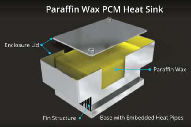
In terms of physical construction, the wax must be contained within an enclosure; two types are most prevalent. In the ¿rst, the wax is encased within an empty container which is usually part of the heat sink base. In the second, the container surrounds a typical ¿n stack. As seen in Figure 2, wax rather than air makes contact with the ¿n stack. When heat needs to be expelled into ambient air outside the container it does so through the outer walls of the enclosure. These can be smooth, as seen above, or ¿nned to add additional surface area.
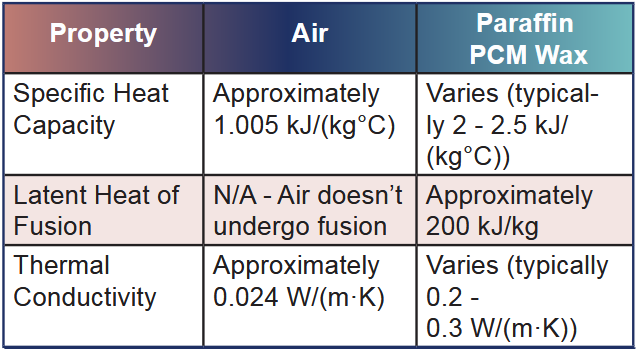
Table 1: Characteristics of Air vs Paraf¿n PCM. Values are approximate and can vary depending on various factors such as pressure, temperature, and the speci¿c composition or type of paraf¿n wax
The fundamental concept (Figure 2) behind a waxbased PCM heat sink is the phase change process. Here’s how it works in steps:
A. Fully Solid Wax: When the device is turned off or at reduced power and the ambient temperature is below the wax melt point the paraf¿n becomes solid and is neither absorbing nor releasing heat.
B. Heat Absorption and Storage: When the elect ronic device or system operates and generates heat, the wax inside the PCM heat sink actively absorbs this thermal energy. As the wax absorbs the heat, it undergoes a phase change from a so lid to a liquid state. This transformation occurs at a relatively constant temperature, facilitated by the high latent heat of fusion of the wax. As a result, a signi¿cant amount of heat is ef¿ciently absorbed and stored during this phase change process.
C. Release of Heat: When the electronic device is turned off, operates at a reduced load, AND the ambient temperature is below the melt point the wax begins to cool down and changes back from a liquid to a solid, releasing the stored heat into the surrounding environment.
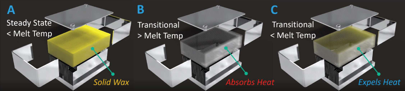
Figure 2: Exploded View of Sealed PCM Heat Sink Through Phase
By reviewing pertinent equations related to steadystate and transient thermal considerations, one can gain a deeper comprehension of how the approach to heat sink design may be modi¿ed. While it is import ant to consider heat transfer through convection and radiation in heat sink design, this section exclusively concentrates on equations pertaining to conduction. In the realm of PCM heat sink design, the emphasis is frequently placed on maximizing conduction to ef fectively manage thermal energy and uphold optimal temperature levels for the cooling of electronic components or systems.
Fourier’s equation, which applies to steady-state heat transfer, tells us that the temperature gradient is proportional to the heat Àow and inversely proportional to both the thermal conductivity and the cross-sectional area. In simpler terms, it means that the temperature gradient (delta-T) depends on how much heat is Àowing, the ability of the material to conduct heat, and the area through which the heat flows.
𝑑𝑇/𝑑𝑥 = -𝑄/𝑘𝐴 (Fourier’s Law)
Here, 𝑑𝑇/𝑑𝑥 represents the temperature gradient, which is the rate of change of temperature with respect to position. 𝑄 is the heat Àow, 𝐴 is the crosssectional area of the bar through which heat Àows, and 𝑘 is the thermal conductivity of the material.
In the steady-state case where there is no change in temperature over time (steady state), the temperature gradient (delta-T) is solely determined by the thermal conductivity. Thermal conductivity quanti¿es how much heat can Àow through the material for a given temperature difference along a length.
For applications like desktop CPUs this makes perfect sense as the device may regularly and for potentially long periods be asked to run at powers at or near their peak. The implication: designing a heat sink to cool higher power inde¿nitely requires some combination of more ¿n area, more base area, more airÀow and/or incorporating some form of pumped liquid cooling.
When the application’s priority is to handle Àuctuations in ambient and/or heat source temperature/ power, rather than aiming for a constant state, the inclusion of additional variables becomes essential. In the case of time-dependent situations, the one-dimensional diffusion partial differential equation (a parabolic PDE) incorporates supplementary parameters:
𝜕𝑇/𝜕𝑡 = 𝛼² * 𝜕² 𝑇/𝜕𝑥 ²
Here, 𝜕𝑇/𝜕𝑡 represents the rate of change of temperature with respect to time (time derivative), 𝜕² 𝑇/𝜕𝑥 ² represents the second derivative of temperature with respect to position (spatial derivative), and 𝛼 is the thermal diffusivity.
The thermal diffusivity (𝛼) is a material property that combines three important properties that indicate how quickly heat can propagate through a material when a temperature gradient is applied. Materials with higher thermal diffusivity conduct heat more readily and tend to respond more quickly to changes in temperature.
𝛼 = 𝑘 / (𝜌 * 𝐶𝑝) (Thermal Diffusivity)
Where:
In transient heat transfer situations, where temperature changes occur over time, the thermal diffusivity governs the rate at which these temperature changes happen within the material. So, the equations describe the behavior of heat transfer by conduction, both in steadystate and time-dependent scenarios and highlight the important material properties that inÀuence heat conduction and its propagation through a material.
In various applications, wax PCM systems offer practical solutions for managing transient conditions. An IC or component in an electronics module may have peak cooling requirements and short duty cycles — often an ideal application for a wax PCM system. An electronics module of small size may also be cooled when transients are applied, such as Wi-Fi modules utilized in aircraft which primarily require cooling during ground transients — can bene¿t enormously from wax-based PCM systems.
Additionally, wax PCMs are versatile and scalable, catering to larger modules as well. Consider the example of outdoor electronic cabinets, which may be exposed to variable thermal loads or solar heat. Implementing wax PCM systems in these scenarios enables engineers to effectively mitigate thermal peaks and avoid overheating, ensuring the reliability and longevity of the equipment.
Generally, PCM heat sinks should be considered under the following conditions:
Condition 1: The thermal load in the system is variable, not steady state, AND the operating conditions risk bringing the maximum electronics temperature above their rated threshold.
Condition 2: Transient heat Àuctuations where exposure time to temperatures below the PCM melt point is signi¿cantly longer than exposure to temperatures above the melt point. A wax PCM system is versatile in terms of power handling, accommodating anything from a couple of watts in localized areas for single components, up to several hundred watts for larger modules. It’s important to consider that the absorbed heat has to be released during the off-cycle, which typically lasts notably longer than the on-cycle — often two to three times as long.
Condition 3: When heat sink compactness is required. Phase change waxes offer compactness and versatility compared to a standard heat sink designed for steadystate operation at the same power level. These materials are typically available in solid or semi-solid forms, making them highly compact and easy to handle. Their physical properties allow for versatile application designs, as they can be incorporated into various shapes and con¿gurations, such as sheets, containers, or encapsulated within other materials.
Condition 4: When a passive cooling solution is required. Phase change wax materials offer a passive cooling method. They do not require an external pow-
er source or active components to operate, making them reliable and maintenance-free. This characteristic is particularly advantageous in remote or off-grid locations, where traditional cooling or heating methods may be limited or unavailable.
While PCM design considerations are largely identical to those for standard heat sinks, there are a few areas that warrant mention. Here are some key factors to consider for the heat sink performance in a wax PCM system.
When insuf¿cient wax is incorporated in a PCM heat sink, it rapidly reaches its fully liquid state limiting its thermal storage capacity — rendering the heat sink ineffective and leading to a sharp rise in system temperature. Consequently, this overheating poses risks to electronic components’ performance and longevity and can cause system failures.
Lastly, the type of wax should be temperature matched to the application requirements. The melt temperature of paraf¿n waxes used in PCM heat sinks varies based on the speci¿c type of wax. The table provides an overview of the melt temperatures and density for various paraf¿n waxes commonly used in PCM heat sinks.
Wax encapsulation in a PCM heat sink is a crucial process that involves containing the wax within a structure that facilitates ef¿cient heat transfer. There are several considerations and methods for encapsulating wax in a PCM heat sink:
Shape and Size of the Encapsulation: The encapsulation can be in various shapes and sizes, such as Àat plates, cylinders, or even microcapsules. The shape and size will affect how quickly the wax can absorb and release heat.
Wax Expansion During Melting: As wax melts, it expands by roughly 15%. The encapsulation must be designed to accommodate this expansion without rupturing or leaking.
Thermal Interface: The interface between the wax and the encapsulating material is important. It should allow for maximum heat transfer. Sometimes, ¿nned structures or porous materials are used inside the encapsulation to increase the surface area for heat transfer.
Sealing: The encapsulation must be sealed properly to prevent leakage of the wax, especially when it is in its liquid phase. The seal should also be able to withstand the thermal cycling without degradation.

Table 2: PCM Wax Melt Temperature
Cooling Down Period: After the wax has melted and absorbed heat, it must be allowed time to cool down and solidify again. The design of the encapsulation should facilitate this cooling process, which may involve passive or active cooling methods.
When the PCM wax in a heat sink doesn’t melt or solidify evenly, it leads to suboptimal performance. Uneven melting can cause localized hotspots where the wax has already turned into liquid, while other parts remain solid. This uneven phase change results in a reduced effective thermal mass that can be utilized for heat absorption, thus compromising the heat sink’s ability to effectively regulate temperature.
To efficiently distribute heat from the heat source through the base of a PCM heat sink, a combination of materials and technologies can be utilized to more evenly spread heat, thus lowering the temperature gradient (delta-T). In order of lowest to highest thermal conductivity, these are aluminum, copper, and either heat pipes or vapor chambers.
By comparing CFD models of heat sinks using these materials, alone or in combination, a clear picture of potential performance gains (lower delta-T) can be understood. While this analysis was not done specifically for a PCM heat sink, it clearly demonstrates how material choice affects heat sink performance. This example uses a 10x10mm heat source dissipating 100W of heat into a heat sink base measuring 150x100mm.
Table 3 compares the delta-T and relative weight of five base options. As expected, higher thermally conductive materials reduce the temperature gradient (delta-T) across the base of the heat sink. While large gains are seen when replacing solid aluminum with solid copper (20°C lower delta-T), the weight of the base roughly triples. Using either an aluminum base with heat pipes or a vapor chamber base eliminates any weight penalty while delivering a substantial improvement to delta-T from the all-copper base option.
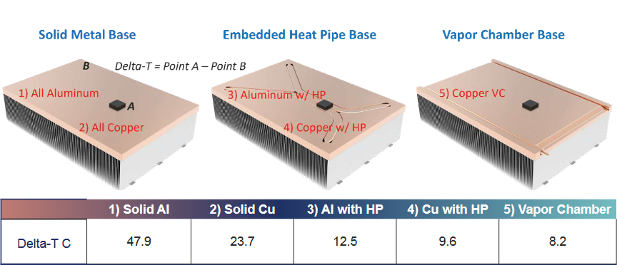
Table 3: Five Heat Sink Base Designs: 1) all aluminum, 2) all copper, 3) aluminum with copper heat pipes, 4) copper with copper heat pipes, 5) copper vapor chambe
Paraffin wax PCM heat sinks provide compact and versatile solutions for managing transient thermal conditions in a wide range of applications. These heat sinks maximize conduction to efficiently regulate temperature by utilizing the high heat capacity and latent heat of fusion of wax. By carefully considering design factors such as wax quantity, encapsulation methods, and heat distribution, PCM heat sinks can effectively absorb and release heat, ensuring optimal thermal management for electronic components or systems.
Maintaining even heat distribution within the heat sink base and the wax material is crucial for effective temperature regulation. By incorporating materials such as copper, aluminum, heat pipes, or vapor chambers, PCM heat sinks can achieve efficient heat transfer and minimize temperature gradients. Overall, PCM heat sink design provides a reliable and compact solution for managing transient thermal conditions and enhancing the cooling performance of electronic devices.