Heat Pipes & Vapor Chambers – What’s the Difference?
Most thermal engineers are going to need a two-phase heat sink using either heat pipes or vapor chambers on numerous projects with which they are involved. Reasons include:
- Keep out zones that prohibit a larger heat sink (thicker base, added fin area, etc.)
- Enclosure size and/or airflow can’t be increased.
- Transitioning to a solid copper heat sink, in whole or in part, adds too much weight and in some cases too much cost.
- Component power /density necessitates heat be moved to a remote location more than 40-50mm away from the heat source.
In today’s blog we’d like to do a topline overview of structural differences and thermal design considerations between these very similar yet somewhat unique two-phase devices. If you need some background on the working principles of two-phase devices, please see our article “How do Heat Pipes Work”.
Structural Design & Cost
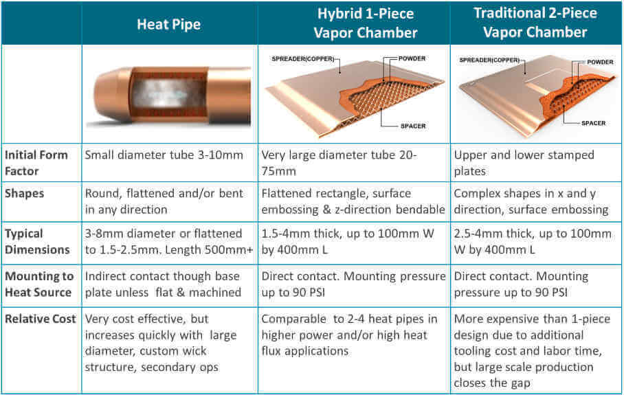
Heat pipes and vapor chambers are composed of the same materials. The most combination is a copper enclosure with a sintered copper wick material. The devices have a small amount of water added and are evacuated to create a partial vacuum. Vapor chambers have an additional support structure (spacer) added for structural integrity and to allow vapor to flow freely.
Unlike heat pipes, which have a width to height aspect ratio on the order of 4:1, vapor chambers can have aspect ratios of 60:1 or more. Additionally, vapor chambers can be divided into two categories: a traditional vapor chamber with two stamped plates forming the upper and lower enclosure and a lower cost hybrid 1-piece vapor chamber that begins the manufacturing process as a very large heat pipe.
Thermal Design Considerations
Heat Pipes
For decades, heat pipes have been the default two-phase device of choice for thermal engineers due largely to the cost delta relative to vapor chambers. They were used both for heat transport, for which they still have an advantage, and for heat spreading, typically using multiple pipes near one another. For lower power applications, perhaps requiring only a single, small heat pipe, or those where heat must be effectively transported, heat pipes keep dominance over vapor chambers due to their low cost and design flexibility.
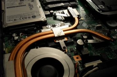
Heat Pipes Cooling Notebook Computer (Wikipedia)
Greater total power and power densities eventually led to heat sinks using multiple heat pipes to solve the thermal challenge. Both images below are heat pipe heat sinks for a small form factor, high performance desktop PC. The one on the left uses a copper base plate in between the heat source and the heat pipes, as is common with heat pipe applications (indirect contact). As processor heat increased in the later generation of this product, the company encountered thermal issues, but did not want to radically redesign the thermal solution as can be seen on the image to the right. Here a vapor chamber replaced the copper base plate, spreading heat more evenly across the heat source and transferring it more effectively to the heat pipes. This is a notable example of how both types of two-phase devices can be used together.
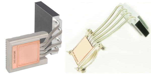
Heat Pipe Heat Sink – (L) Using Solid Copper Baseplate, (R) Using Vapor Chamber (ixbtlabs.com & Celsia)
A potential alternative to this problem might have been to implement ‘direct contact’ heat pipes. But this solution has its drawbacks as well. As seen below, this design choice uses slightly flattened and machined heat pipes embedded in an aluminum mounting bracket to make direct contact with the heat source. While eliminating the base plate and added TIM layer – decreasing thermal resistance – it doesn’t spread the heat as effectively as a vapor chamber heat sink solution.
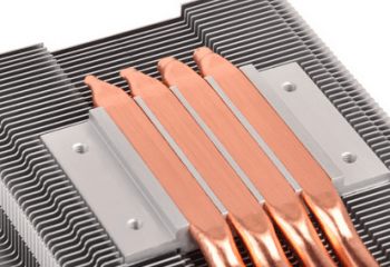
Direct Contact Heat Pipes (Silverstonetek)
Traditional (2-Piece) Vapor Chamber
Most manufacturers of vapor chambers use a traditional two-piece design. Studies and practical applications show that the performance of heat sinks using vapor chambers can be enhanced by 20-30% over their heat pipe counterparts. A two-piece vapor chamber design has cost implications of roughly the same magnitude versus a multiple heat pipe configuration. Nonetheless, vapor chamber usage has grown with increasing total powers, higher power densities, and space constraints of today’s devices.
Because vapor chambers do an incredible job of spreading heat, allow for low-profile heat sinks, can be made into virtually any shape, embossed, and make direct contact with one or multiple heat sources, these devices are used in a wide variety of higher power applications. Below are two examples of heat sinks using two-piece vapor chambers.

Traditional Two-Piece Vapor Chamber (anandtech.com & Celsia)
As mentioned earlier, the increased cost of this design sometimes limits its incorporation into thermal solutions. Another potential drawback is that there’s little design flexibility in the z-direction. Making a U-shape for instance, while conceivably possible, would be impractical from a manufacturability/cost perspective.
Hybrid (1-Piece) Vapor Chamber
One-piece vapor chambers are a cost-reduced version of their two-piece counterparts yet keep the thermal performance characteristics while adding some unique capabilities (e.g., U-shape bending). Like heat pipes, a one-piece vapor chamber begins its life as a single copper tube, hence the 1-piece moniker. Like traditional two-piece vapor chambers, one-piece vapor chambers make direct contact with the heat source, have a multi-directional heat flow, and can support clamping forces of up to 90 PSI. But they’re less expensive to produce because they need less tooling, don’t use individual support posts, and don’t have to be welded on all four sides. Below are a few examples of one-piece vapor chambers.

Hybrid One-Piece Vapor Chambers
The thing to remember about two-phase devices is that heat pipes favor moving heat over spreading it, while the reverse is true of vapor chambers. There are many thermal challenges where either could be used with satisfactory results so it’s important to do a thorough review process of both designs before settling on one.
Please contact us, if you’d like to learn more about how Celsia can help with your next heat sink project. We’ve worked on everything from consumer devices to industrial test equipment that require heat sinks to cool anywhere from a few watts to a few kilowatts.


