Vapor Chamber
Vapor chambers, also known as planar heat pipes or heat spreaders, are two-phase devices with a large, flat surface that efficiently spread heat from high power or high heat flux electronics. Typically used in place of the base plate in a standard metal heat sink or heat pipe in a two-phase heat sink, these devices can reduce the conduction loss (Delta-T) in a thermal assembly by 50% or more, resulting in a solution with lower overall thermal resistance.
Vapor chamber use has surged in recent years, largely due to increases in power density resulting from shrinking die size. Notably, modern-day vapor chambers offer improved capabilities and lower costs compared to those available just a decade ago, enhancing their price-performance value proposition and application flexibility.
Topics
- Vapor Chamber Technology
- Types of Vapor Chambers
- Vapor Chamber Usage Overview
- Performance of Vapor Chamber Heat Sinks
Vapor Chamber Technology
While vapor chambers are a type of heat pipe, sharing the same operating principles, their design and usage make them much more than simply a flat heat pipe. Manufacturing traditional vapor chambers involves two stamped metal plates that mirror each other in shape, allowing for a range of designs from a basic square to more complex configurations. While vapor chambers typically don’t exceed 400mm for electronics cooling applications, they can be made as wide as 150mm offering an expansive surface area from which to dissipate heat. Additionally, each of the two plates can have embossments or reliefs stamped into the design, allowing the device to better accommodate variations in component height along the PCB.
The increased design flexibility of vapor chambers makes them more versatile for various applications. However, their manufacturing process is more complex, resulting in higher production costs compared to heat pipes which begin production as a simple tube. Recently, a new method of vapor chamber production has emerged, which has significantly reduced both manufacturing complexity and cost – more on this later.
The wick options for vapor chambers are identical to those of heat pipes, including sintered, grooved, and mesh/bundled fiber wicks. As vapor chambers are usually chosen for their superior performance versus heat pipes, sintered wicks are the most commonly used structure. Specifically, water-based vapor chambers with a copper enclosure and copper sintered wick are the most prevalent.
Using two stamped plates in the manufacturing process, the wick design within a single vapor chamber can be more intricate, allowing for a device that is precisely tailored to a specific application. The most highly customizable wick structure, a sintered wick, can include various design features within a single device, such as:
- Variation in wick thickness – wick structures, especially sintered wicks, are the ‘pumps’ that move liquid to the evaporator. Increasing their thickness provides more pumping power, but at the expense of vapor space; the heat/vapor transport highway.
- Variation in wick porosity / permeability – Increasing the pore spacing in between the sintered material results in a less densely packed structure, allowing water to move though it more easily. This is good for applications where the condenser is level with or above the evaporator.
- Ability to shape the wick in certain sections of the device – some applications require a vapor chamber that is capable of moving a high volume of liquid back to the evaporator (thicker wick) while lowering evaporator resistance to improve overall performance. Here, the wick section at the evaporator is either thinned or has grooves in it allowing the liquid to vaporize more easily. As the lower evaporation delta-T is counted in the overall heat sink delta-T, total thermal performance is improved.
Once the wick is in place, metal columns or a spacer is added to improve structural rigidity while allowing vapor to move freely. Finally, the two halves of the vapor chamber are diffusion bonded together and a small tube used for fluid-fill is inserted. One of the same working fluids used for heat pipes is introduced to the vessel and evacuated to form a vacuum before being sealed.
Working principles for vapor chambers and heat pipes are the same. As heat is introduced to the evaporator area, usually the center of one side of the device, the working fluid turns to vapor which moves to areas of lower pressure. The condenser area, usually a finned structure, cools the vapor where it condenses back to a liquid which is absorbed by the wick and returned via capillary action to the heat source area.
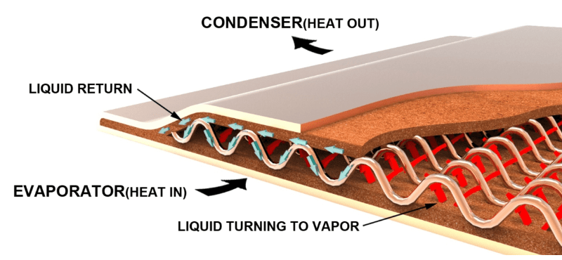
Vapor Chamber Cutaway: Working Principles
Types of Vapor Chambers
There are several categories of vapor chambers, each with its own advantages and disadvantages. These include the traditional ‘two-piece’ design, a lower cost ‘one piece’ alternative, ultra-thin vapor chambers, and machined vapor chambers. All operate under the same principles and offer the same material and fluid choices but are used for different application challenges.
Versatile Two-Piece Vapor Chamber
The type of vapor chamber discussed to this point is the traditional variety that uses two stamped plates, thus the ‘two-piece’ moniker.

2-Piece Vapor Chamber & Heat Sink Assembly
The advantages of traditional vapor chambers are:
- Direct contact with the heat source removes the base-plate layer of thermal resistance found in most heat pipe applications.
- High degree of flexibility in shape. Shapes are determined by the application requirements and PCB board layout yet tempered by the inherent limitations of the metal stamping process. The precise shape is usually dictated by the need to maximize surface area while avoiding other components on the PCB.
- Easily incorporate through holes along the outer edge or even in the middle of the device provides for flexible mounting options to the PCB.
- High degree of flexibility of wick design within a single device. Varying wick thickness, wick porosity, and wick shape within a single vapor chamber optimizes the trade-offs in operational characteristics such as power handling capacity (Qmax), the ability of the device to transport working fluid against gravity, the ease with which the working fluid turns to vapor at the evaporator area, and the ability to handle higher heat flux.
- Easily accessible in the market. Any heat pipe manufacturer likely also produces this type of vapor chamber as it was the first production method used for these devices.
Disadvantages include the higher cost versus heat pipes and other vapor chamber designs, limited height & angle bending in the Z-direction (up and down), and longer lead times.
Low Cost One-Piece Vapor Chamber
Pioneered by Celsia in the early 2000’s, one-piece vapor chambers begin the production process as a very large single tube (1-piece) and while offering exceptional thermal performance and some unique design options.
Starting from large diameter tube stock, a wicking structure is bonded to the inside walls using various density and porosity formulations. Then a wafer-thin perforated spacer is inserted to aid in vapor flow and increase structural rigidity. As with all two-phase devices, a liquid is added and the device is vacuum sealed. This process requires no stamping or machining and reduces the number of secondary operations, driving costs down to near parity with heat pipe solutions.
The advantages of one-piece vapor chambers are:
- Direct contact with the heat source removes the base-plate layer of thermal resistance found in most heat pipe applications.
- Lower cost relative to 2-piece vapor chamber designs yet still allowing higher performance than multi-heat pipe solutions for near cost parity.
- Quicker time to prototype as the production process is simpler.
- Ability to bend the device, post-production, in L and U-shapes to increase design options versus a traditional two-piece design.
- Although they are basically flattened heat pipes, these vapor chambers can be as wide as 110mm and offer a width-to-height ratio of 30:1, far exceeding the 4:1 ratio of flattened heat pipes.
One-piece designs are disadvantaged in several ways. First, designers are limited to rectangular shapes. Second, the wick structure within a single device must be uniform in thickness, porosity, and shape/design limiting the degree to which it can be customized. Third, through holes are more difficult to implement.
Ultra-Thin Vapor Chambers
Thin and ultra-thin vapor chambers can be a 1-piece or 2-piece design and are only included as a separate category because of their increasing use in compact devices like smartphones. Thermal engineers must becareful to recalibrate their performance and design expectations when using vapor chambers below 2mm.
Typical vapor chambers are generally 2.5-4mm in height depending on size and power requirements. They are known for their ability to handle higher total power and higher heat fluxes than their heat pipe counterparts. Moving below 2mm requires some consequential changes to its physical design.
- Enclosure wall thickness needs to be reduced resulting in a weaker structure that can deform more easily.
- Sintered wicks are deposited on only one side of the internal structure to optimize the ratio of wick and vapor space.
- Mesh or bundled fiber metal wicks used in place of sintered material further reduce the angle at which the device can operate against gravity and limits the power density the VC can support.
The vapor space becomes a limiting factor. For thicker vapor chambers the amount of space for vapor to transport heat to all areas of the vapor chamber is in abundance, resulting in the high-power handling capacity. By seriously limiting this volume, Qmax drops substantially.
Machined Vapor Chambers
A machined vapor chamber is a specialty design that operates as a thermal hub to which multiple heat sources, usually high power / high flux components, can be attached in order to save space and/or utilize a single condenser.
In this example, three heat sources are screwed to the outer walls of the device and a cold plate to another surface. Another application for machined vapor chambers is with extremely recessed heat sources that, due to high power output, require a very large block or cylinder interface with it.
3D Vapor Chamber
A relatively new addition to this category family is the 3D vapor chamber. This design aims to combine the best of heat pipes and vapor chambers. Here, the base of the heat sink is a vapor chamber with holes in the top to which open-ended heat pipes are welded. The advantage is a very large contiguous vapor space that achieves a lower delta-T than its vapor chamber plus heat pipes alternative.
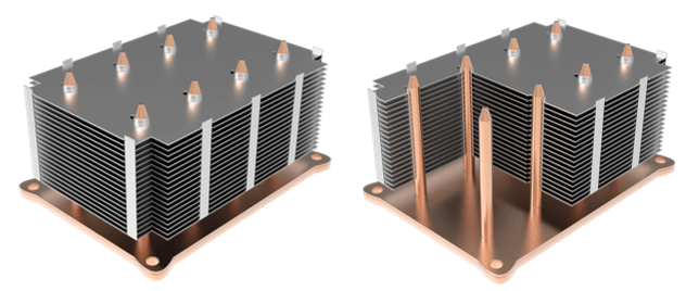
3D Vapor Chamber Heat Sink
The downsides of 3D vapor chambers include large cost increases due to the complexity of the manufacturing process and the introduction of a point of failure at the weld line of the vapor chamber and heat pipe.
Vapor Chamber Usage Overview
In cases where standard solid-base, finned heat sinks fail to meet thermal, mechanical or dimensional requirements, the addition of a vapor chamber to the thermal solution can often provide a viable solution. A comprehensive vapor chamber design guide and vapor chambers versus heat pipes blog outline several broad indicators of when this is likely to occur.
- Conduction-limited applications – High power density and/or high total power can cause a traditional heat sink to become conduction-limited, resulting in a high heat sink temperature rise (delta-T). Vapor chambers, with their high thermal conductivity and large surface area, can help minimize heat sink conduction losses while efficiently dissipating heat away from the evaporator.
- In thermal applications that require several heat sources to remain at roughly the same temperature to one another (isothermal applications), vapor chambers are used.
- In vertically space-constrained applications the low thermal resistance of vapor chambers allows them to replace a thicker solid metal base, leaving more room for fin height.
- In environments with limited airflow, additional horizontal fin area is required to dissipate heat, versus one with high airflow. Vapor chambers allow engineers to reduce conduction resistance in the base allowing more even heat distribution to the fins.
- When weight is important – Furthermore, if weight restrictions apply to a device due to shock and vibration or payload requirements, a heat sink with a solid metal base may not be feasible. Vapor chamber-based heat sinks can be considerably lighter than the alternative solid metal heat sink.
Vapor Chamber Heat Sink Design & Performance
As seen in the figure below, vapor chambers can be used to spread heat to a local condenser or move it to a remote one. However, spreading heat is by far the most common use of vapor chambers. Heat pipes are usually used when heat needs to be moved to a remote condenser.
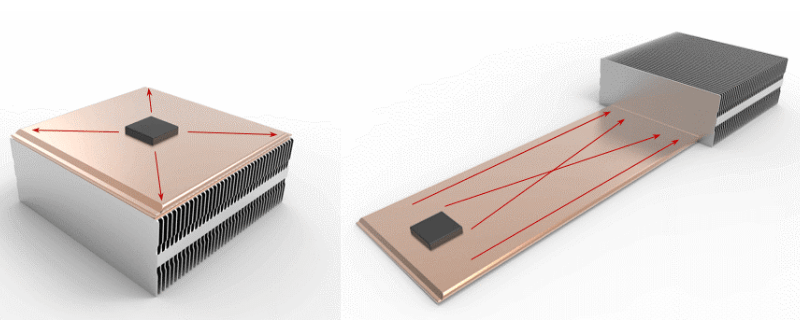
Vapor Chamber Most Often Spreads Heat | Sometimes Move Heat
Vapor chambers can be paired with any type of heat sink. Extruded fin vapor chamber heat sinks are the most common for lower power applications (~<100W) due to their relatively low cost and reasonable thermal properties. Forced air applications allow tighter fin spacing for higher power applications in order to maximize fin area. In these cases, zipper fins or fin packs are most used because of their design versatility and lower price relative to skived or bonded versions.
Vapor chambers can be attached to the fin base using a variety of methods, depending on the specific design and application requirements. Here are some common approaches:
- Soldering: The most common approach is to use solder to attach the vapor chamber to the fin base. Soldering provides a strong bond and good thermal conductivity but requires the device to be nickel plated for solder compatibility. Solders that melt at lower temperatures are preferable because higher temperature alternatives may cause the vapor chambers to deform unless it is encased in a solder jig.
- Adhesive bonding: One common approach is to use a thermally conductive adhesive to attach the vapor chamber to the fin base. This approach is relatively simple and can be used with a wide range of fin base materials however it is the least thermally efficient.
- Mechanical attachment: Mechanical attachment methods include using screws, clips, or clamps to attach the vapor chamber to the fin base. This approach provides the most secure connection to meet challenging shock and vibration requirements.
Similar to heat pipes, the effective thermal conductivity of vapor chambers depends on several factors, primarily the distance that heat is moved away from the heat source. When comparing the effective thermal conductivity of heat pipes to vapor chambers for the same application, it is important to note that, despite having a lower effective thermal conductivity, vapor chambers can outperform heat pipes. This may seem counterintuitive, but it is due to the additional cross-sectional area of the vapor chamber as compared to heat pipes.
When properly designed for the application, thermal solutions using vapor chambers outperform both solid metal and heat pipe based alternatives. Borne out by real-world testing, two different CFD thermal models illustrate the differences.
In the first, we look at a CFD comparison between heat sinks with the condenser attached to the base in an application that needs a ‘local’ fin stack. Both a solid aluminum base and a solid copper base are compared with a vapor chamber base.
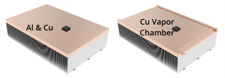
Heat Sink Design Options: Aluminum Base, Copper Base, Vapor Chamber Base
The thermal resistance for the aluminum and copper are 0.587 oC/W and 0.382 oC/W respectively, while the vapor chamber design is 0.260 oC/W. Further, while the aluminum and vapor chamber heat sinks are roughly the same weight, the solid copper heat sink is nearly twice as heavy.
To more closely compare the thermal performance of a vapor chamber heat sink to a solid metal heat sink visit our online heat sink calculator and usage instructions for that calculator.
In the second example a heat pipe based heat sink is compared to one with a vapor chamber in an application where the fin stack is remote to the heat sink base.
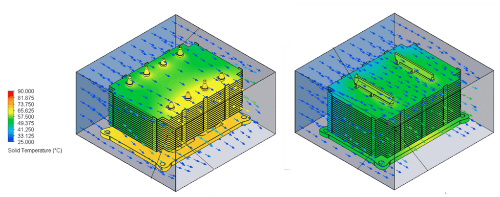
Comparison: Heat Pipe Heat Sink vs Vapor Chamber Heat Sink
For this 250W application, the heat pipe solution has a delta-T of 54 oC while the vapor chamber heat sink registers at just under 39 oC.
In conclusion, vapor chambers are a highly effective and efficient cooling solution for a wide range of electronic devices. Their unique design, high thermal conductivity, and customizable wick structure make them an ideal choice for applications with high power density, limited space, and/or low airflow. While the manufacturing process for vapor chambers is more complex and expensive than that of heat pipes, recent advancements have reduced production costs and increased design flexibility. By optimizing the design of the vapor chamber and integrating it into the heat sink assembly, it is possible to achieve excellent thermal performance and cost-effectiveness. As electronic devices continue to become smaller and more powerful, vapor chambers are likely to play an increasingly important role in thermal management solutions.

