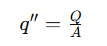
High heat flux cooling challenges emerge when power density increases faster than the available area available to reject heat. As semiconductor geometries shrink and devices push toward high power density, localized heat concentration increases rapidly within the thermal stack.
Above roughly 100 W/cm², thermal performance is often limited less by the fin stack itself and more by the ability to spread heat away from a concentrated source. In this regime, spreading resistance within the base becomes a primary design constraint.
As heat flux increases, solid metal conduction becomes less efficient at distributing heat uniformly across the cooling surface. Temperature gradients rise near the source, localized hotspots develop, and downstream cooling surfaces become underutilized because heat cannot spread effectively before rejection.
High heat flux thermal management is fundamentally a heat spreading and transport problem before it becomes a heat rejection problem.
Why Conventional Cooling Stops Scaling
Traditional heat sinks rely on conduction through aluminum or copper bases to move heat from the source into the fin structure. At moderate heat flux levels, this works well because heat can spread across the available cooling area before rejection.
As source sizes shrink and power density increases, that changes. A small, concentrated heat source must spread laterally through solid metal before convection can remove it. This creates localized thermal resistance near the source commonly referred to as spreading resistance.
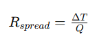
In many high heat flux designs, spreading resistance in the base becomes the dominant thermal constraint. Increasing copper thickness adds mass and cost but delivers diminishing returns because conduction through solid metal remains diffusion limited. As heat flux rises, thermal limitations increasingly shift into the spreader and interface layers before the downstream fin structure can fully utilize its available cooling capacity.
The result is:
- elevated junction temperatures
- localized hotspots
- thermal gradients across the base
- inefficient fin utilization
- reduced thermal margin
In high heat flux systems, the spreader often becomes more important than the fin stack itself.
How Two-Phase Cooling Solves High Heat Flux Problems
Two-phase cooling technologies solve high heat flux problems by changing how heat moves through the thermal path. Instead of relying only on solid metal conduction, two-phase devices use liquid evaporation and vapor transport to spread heat rapidly across a larger surface area.
Different high heat flux cooling technologies address different transport and spreading constraints. Two-phase architectures are particularly effective in mechanically constrained designs where limited z-height, irregular geometry, component spacing, or orientation changes restrict direct thermal paths and reduce the effectiveness of conventional solid-metal spreading alone.
Heat pipes and vapor chambers absorb concentrated heat at the evaporator region, convert the working fluid into vapor, transport that vapor to cooler regions, and condense it across a larger condenser surface. This process creates extremely efficient lateral heat spreading with far lower temperature gradients than solid copper alone.
For fixed-orientation, higher-power systems, thermosiphons use gravity-assisted return flow to support larger passive transport capacity without wick limitations. Phase change materials (PCMs) are often integrated alongside two-phase cooling architectures to absorb short-duration thermal excursions and stabilize temperature rise before heat reaches the primary heat rejection surface.
As local heat flux increases, two-phase spreading becomes valuable because it reduces the temperature rise associated with concentrated heat input. Rather than allowing heat to remain localized near the die, vapor chambers and heat pipes distribute thermal energy across a much larger effective area before it reaches the fin stack, chassis wall, or cold plate.
This improves:
- thermal uniformity
- effective utilization of downstream cooling surfaces
- junction temperature control
- transient response
- packaging efficiency
- system reliability in constrained environments
Two-phase cooling does not replace the rest of the cooling system. It improves the transport and spreading portion of the thermal path so the downstream heat rejection system can operate more effectively.
High Heat Flux System Architectures
High heat flux electronics cooling challenges appear across RF, defense, telecom, aerospace, and other power-dense systems where localized heat concentration exceeds the practical limits of conventional conduction cooling.
RF & Microwave Electronics
Localized package heat flux in RF power amplifiers commonly exceeds 100 W/cm², where spreading resistance within conventional copper bases begins limiting downstream heat sink effectiveness. Vapor chambers are frequently integrated beneath PA modules to reduce thermal resistance, improve heat spreading, and distribute heat more uniformly into the attached cooling structure.
Ruggedized & Defense Systems
Passive two-phase cooling architectures are commonly used where high localized heat flux, constrained airflow, and environmental qualification requirements limit active cooling approaches. Sintered-wick heat pipes and vapor chambers support efficient thermal transport across mechanically constrained systems while maintaining low thermal resistance through the spreading and transport path.
Aerospace Electronics
Aerospace thermal systems often operate with strict mass, volume, and reliability constraints while managing high localized heat flux within low-air-density or sealed environments. Reduced convection effectiveness at altitude increases reliance on efficient heat spreading and transport through the thermal stack before heat reaches the downstream cooling surface.
Sealed Outdoor Electronics
Fanless outdoor electronics often operate with narrow thermal margins and limited convection capability. Vapor chambers paired with high-aspect-ratio fin structures improve utilization of passive cooling surfaces by spreading concentrated heat loads more uniformly across the heat sink base and external enclosure surfaces.
Working With Celsia
High heat flux thermal architectures are shaped by more than total power alone. Thermal performance, mechanical constraints, cooling method, and environmental requirements all influence the appropriate high heat flux cooling solution.
Five factors typically drive the architecture decision:
- Heat flux and total power: Localized W/cm² determines the spreading and transport architecture, while total heat load determines the required downstream cooling capacity.
- Geometry and packaging constraints: Available z-height, footprint, component spacing, and mechanical obstructions influence whether vapor chambers, embedded heat pipes, or remote transport paths are appropriate.
- Cooling method: Forced air, natural convection, conduction-to-chassis, and liquid-cooled systems each impose different thermal resistance and condenser-side limitations.
- Thermal budget: As allowable junction-to-ambient temperature margin decreases, spreading resistance and transport efficiency become increasingly important within the thermal stack.
- Environmental and reliability requirements: Shock, vibration, altitude, orientation, thermal cycling, ingress protection, and qualification requirements all affect thermal architecture selection and material compatibility.
For early-stage evaluation, engineers can use our spreading resistance calculator and heat sink calculator to estimate first-pass thermal resistance and heat spreading behavior before detailed design analysis.
Programs move through CFD-driven concept evaluation, prototype fabrication, and thermal characterization to validate spreading performance, thermal resistance, and integration within the intended operating environment.
See Certifications & Compliance →