Vapor chamber cooling design is a common approach for high-power electronics where heat pipes limit system performance. This guide covers the most prevalent applications:
- CPU/ASIC to amplifier designs with power ranging from roughly 20 to 250 watts
- Power density above 20 W/cm2
- Heat source sizes between 10mm and 30mm square
What is a vapor chamber cooling system? It is a sealed, flat two-phase device that spreads heat across a large surface area using the evaporation and condensation of a working fluid. The focus here is on vapor chamber cooling system designs using a copper envelope with sintered copper wick and water as the working fluid. This allows engineers to manage higher heat loads more efficiently, improving thermal performance in compact, high-power electronic systems.
Below, we review the following topics:
- How Does Vapor Chamber Cooling Work
- Vapor Chamber Cooling Design Parameters
- Vapor Chamber VS Heat Pipe
- Types of Vapor Chamber Design
- Vapor Chamber Usage
- Vapor Chamber Thermal Conductivity & Performance
- Vapor Chamber Heat Sink Integration
- Dimensional Design Limits of Vapor Chambers
Request a Custom Vapor Chamber Quote
How Does Vapor Chamber Cooling Work
A vapor chamber works on the same two-phase principle as a heat pipe, but in a planar geometry. Heat applied to the evaporator surface causes the working fluid to vaporize. That vapor spreads across the internal cavity, condenses on the cooler condenser surface, releases its latent heat, and wicks back to the evaporator to repeat the cycle. The flat geometry allows two-dimensional heat spreading, making vapor chambers far more effective than solid metal bases at reducing hot-spot temperatures across large heat sink footprints.
Vapor Chamber Cooling Design Parameters
The following guidelines apply to electronics cooling using vapor chambers.
Power Handling Capacity
Vapor chambers can match the power handling capacity of multiple heat pipes, from a few watts to over a kilowatt. That said, if a single heat pipe can meet both thermal and physical requirements, it is likely the more cost-effective choice, depending on post-production operations like machining. The move from heat pipes to vapor chambers typically comes with applications requiring higher power, higher power density, or both.
Power Density Capacity
Vapor chambers are well-suited for electronics cooling where power density falls roughly between 20 W/cm2 and 500 W/cm2. In these situations, it is usually critical that heat spreads quickly to a larger surface area.
Shapes & Dimensions
The traditional method for producing vapor chambers starts with two stamped plates, mirror images of each other, that are diffusion-bonded together. This gives designers considerable leeway in the X and Y dimensions. Length and width maximums are governed by press and furnace size as well as application requirements. As a result, vapor chambers rarely exceed around 300 x 400mm.

Some manufacturers also produce vapor chambers from a large copper tube (25 to 70mm diameter) that is sintered, flattened, and fitted with an internal support structure. We call these 1-piece vapor chambers. The main advantages are cost and the ability to form L and U configurations. The drawback is that they are limited to rectangular shapes, with typical dimensional limits of 100mm wide by 300mm long. Both types, particularly when designed with a sintered wick, are 2.5 to 4mm thick depending on the power to be moved or spread.
Bending
Two-piece vapor chambers made from stamped plates are generally not bent post-stamping. Any small steps or bends are incorporated during the stamping process. One-piece vapor chambers that start as a tube can be bent post-production. While bend radius varies with width, thickness, and bend location, a typical bend radius ranges from around 7mm for smaller units to 12mm for larger ones. For more details, see the dimensional design limits section at the end of this guide.

Surface Flatness
Surface flatness is particularly important for vapor chambers because, unlike heat pipes, they are designed to make direct contact with the heat source. Flatness in the component contact area is controlled to a nominal 0.002″/1″. Post-machining can bring this down to 0.001″/1″, though the added cost is typically only warranted when mating to higher-power-density components where a thin bond line and low interface resistance are critical.

Resistance to Heat Loads
Without modifications, vapor chambers can withstand deformation up to around 110°C. To handle higher temperatures, wall thickness must be increased, additional internal supports added, or an exoskeleton plate used on one side. For comparison, heat pipes can withstand up to 200°C due to their inherently stronger cylindrical geometry.

Clamping Pressure
Vapor chambers are hollow and require internal support to withstand clamping pressure. Standard designs handle up to 60 psi before deforming. Modified designs can support up to 90 psi.
Surface Treatment
All copper parts are passivated to protect against short-term discoloration. Nickel plating is the most common coating for both heat pipes and vapor chambers, used for corrosion protection or cosmetic reasons.
Vapor Chamber VS Heat Pipe
Vapor chambers differ from heat pipes in several key ways. First, they are more isothermal than either solid metal or heat pipe solutions. This produces a more uniform temperature across the die face (reducing hot spots) as well as a lower delta-T across the full vapor chamber surface.

Second, heat sinks using a vapor chamber allow direct contact between the heat source and the device, reducing interface thermal resistance. Heat pipe solutions typically require an additional base plate and TIM layer.
Third, height-constrained thermal solutions often benefit from vapor chambers because they produce a thinner base for the fin stack and can allow more fin area, since heat pipes typically run through the center of the fin stack.
Types of Vapor Chamber Design
While the traditional two-piece vapor chamber made from two stamped plates is the most familiar, a second manufacturing method offers distinct advantages for certain applications.
A 2-piece vapor chamber is required for shapes other than a rectangle, since the stamped plates can be created in virtually any shape along the XY plane. They also support higher embossments when the heat source is recessed. The trade-off is a slight cost premium over 1-piece and the inability to be bent post-production.

A 1-piece vapor chamber begins as a single large copper tube that is flattened and fitted with a corrugated spacer for structural support. Its shape is limited to a rectangle, but it can be bent in the Z-direction to form steps, L-shapes, or U-shapes.

Vapor Chamber Cooling System Usage Guidelines
Use a vapor chamber when the heat sink design is conduction-limited. The following rules of thumb will help determine whether a vapor chamber cooling design is the right call, along with links to online calculators.
Use a Vapor Chamber When the Thermal Budget is Tight
The thermal budget is the maximum ambient operating temperature minus the maximum component case temperature (Tcase). For many outdoor or ruggedized applications, thermal budgets can fall well below 40°C.
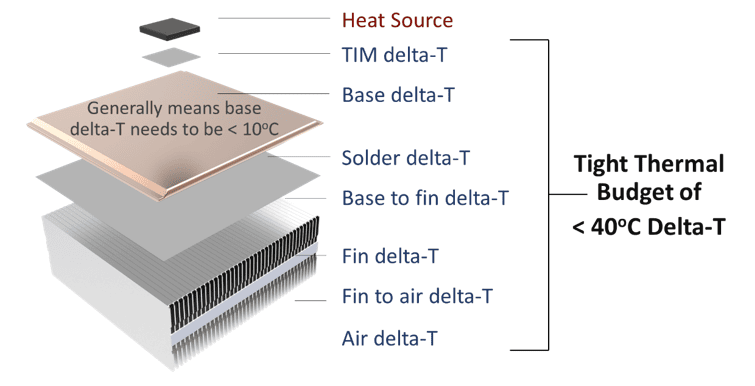
That means the sum of all individual delta-Ts from TIM to air must stay below the thermal budget. For typical applications in this category, the delta-T of the heat sink base should be 10°C or less. Use Celsia’s online heat sink calculators to help determine whether a vapor chamber is the right replacement for a solid aluminum or copper base:
- Estimate Required Heat Sink Size: Quickly estimates total heat sink volume for a rough sense of required dimensions. See the use instructions and the heat sink size calculator.
- Compare Vapor Chamber Base to Solid Metal: Shows each delta-T in a heat sink assembly and compares vapor chamber bases to solid aluminum or copper. See the vapor chamber vs metal base heat sink calculator and use instructions.
When the Vapor Chamber-to-Evaporator Area Ratio is Greater Than 10:1
Like heat pipes, vapor chamber thermal conductivity increases with length. A vapor chamber the same size as the heat source offers little advantage over solid copper. A good rule of thumb: the vapor chamber area should be at least 10x the heat source area. When the thermal budget is generous or high airflow drives a compact fin stack, this ratio may be less critical. In many applications, however, the heat sink base needs to be considerably larger than the heat source.

Use a Vapor Chamber When the Primary Goal Is to Spread Heat
While vapor chambers can sometimes move heat to a remote heat sink, they are most often used to spread heat to a local one. Heat pipes are better suited for connecting a heat source to a remote fin stack, particularly when that path involves twists and turns. 
Vapor Chamber Thermal Conductivity & Performance
When comparing effective thermal conductivities, vapor chambers appear to have lower thermal resistance than heat pipes. This is due to the substantially larger cross-sectional area. A typical 6mm heat pipe has a cross-section of 28mm2, while even a small vapor chamber measuring 3mm x 40mm has a cross-section of 120mm2 (dT = Q x L / (k x A)).
When transporting the same power, effective thermal conductivity decreases by the ratio of the cross-sections. The key point: although a vapor chamber has lower effective conductivity, a well-designed vapor chamber cooling system offers meaningful performance advantages, including higher total capacity, better operation against gravity, direct contact with the heat source, and lower delta-Ts overall.
Vapor Chamber Heat Sink Integration
Vapor chambers can be attached to any heat sink type (extruded, skived, etc.), but are most often paired with zipper fins (fin packs) or machined heat sinks. Both offer strong thermal performance: zipper fins from their thin, closely spaced fins, and machined heat sinks from their virtually unlimited geometric flexibility. In some extreme environments, die-cast housings with integrated fins are also used successfully.

Regardless of heat sink type, vapor chambers must be bonded to the base or fins. Soldering is the most common method and offers better thermal conductivity. Solders used in these assemblies typically have thermal conductivities in the range of 20 to 50 W/mK. Epoxies run at roughly one-tenth of that value, making them suitable only for low-power-density applications below 10 W/cm2.

Soldering occurs at temperatures that generally exceed the vapor chamber’s maximum operating temperature, so fixture design is critical. Solder fixtures must withstand the internal pressures generated inside the vapor chamber during the soldering process to prevent deformation. The pressure chart below shows internal vapor chamber pressure versus temperature.

The solder fixture (shown in purple) is designed to conform to the heat sink assembly profile, preventing deformation during soldering. The upper and lower portions are clamped or bolted together to restrain the vapor chamber from expanding. 
Celsia Vapor Chamber Dimensional Design Limits
The table below lists specifications and tolerances for 1-piece vapor chambers. Because these begin as a large tube, the diameter is listed first, followed by widths at various thicknesses and associated tolerances. No equivalent table is provided for 2-piece vapor chambers due to the range of configurations they can assume, though similar tolerances apply. For 2-piece designs, 300 x 300mm is the largest possible form factor, with 75 x 150mm being the most common. 
Let’s Solve Your Thermal Challenge
Vapor chamber cooling design is the right choice when heat pipes alone can’t keep pace with power density, thermal budget, or form factor constraints. Understanding when to specify a vapor chamber, which construction method to use, and how to pair it with the right heat sink type are the decisions that determine whether a thermal solution succeeds. If you’re working through those tradeoffs, our engineering team is ready to help.
Contact Celsia to discuss your next thermal design challenge. We specialize in custom heat pipes, vapor chambers, and complete heat sink assemblies for aerospace, defense, telecom, and industrial applications.