The focus of this heat pipe design guide is on sintered copper heat pipes (w/water) for electronics cooling applications. This typically translates to dissipated heat of between 20-200 watts (less if power density is high) and power density up to around 25 W/cm2.
This heat pipe design guide will cover the following topics:
- Typical Uses of Heat Pipes
- Heat Pipe Specifications & Tolerances
- Heat Pipe Performance: Sintered Copper Wick & Heat Pipe Carrying Capacity
- Secondary Operations Performed on Heat Pipe Designs
- Heat Pipe Selection Example
- Heat Pipe Design Guidance for Heat Sink Integration
- Heat Pipe Modeling Tips
Typical Uses of Heat Pipes
Used properly, and under the right conditions, heat pipes dramatically improve heat sink performance. This design reality is due to the very high thermal conductivity of heat pipes; generally between 10-100 times that of solid copper. Unlike solid metal, heat pipe thermal conductivity changes with several variables – length being the most notable. Consequently, very short heat pipes of 50mm or less have thermal properties that might be better served by using solid copper or aluminum. Here are the most common usage configurations for heat pipes as part of a heat sink assembly:
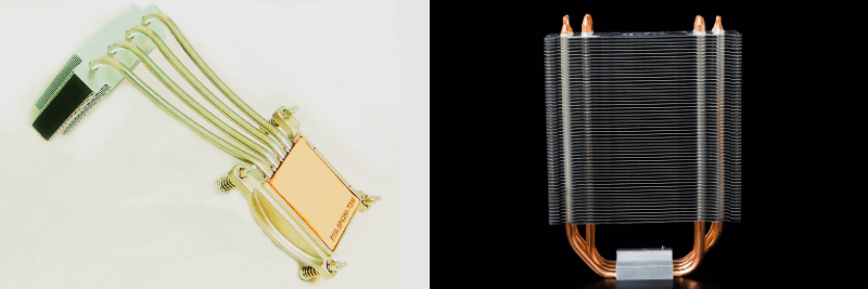
Moving Heat to a Remote Heat Sink
Heat pipes are used to move heat, in any direction or orientation, from the heat source (evaporator) to the heat sink (condenser). Pictured below are a couple of examples.
Spreading Heat to a Local Heat Sink
When a two-phase device is needed yet cost is a driving factor, heat pipes can be used to spread heat to a local heat sink. A vapor chamber in either of these two applications will reduce the total heat sink delta-T by 4-9 oC . The improvement is due to the lower thermal resistance of a vapor chamber as well as the way it interfaces with the heat source (direct contact). Note that both these examples use a solid copper spreader that attaches to the heat source, then heat moves to the heat pipes (indirect contact).
Heat Pipe Specifications & Tolerances
The theoretical operating temperature limits of sintered copper water heat pipes are 0-250 oC, although in practice heat pipes don’t really start to operate until around 20 oC. Below 0 oC, the water freezes within the sintered wick structure but causes no damage due to expansion as the amount of liquid is so small. For example, a typical 6mm heat pipe that’s 150mm in length contains about 1cc of water.
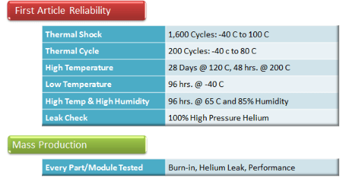
A quick note on heat pipe reliability. Heat pipes have been extensively tested for decades. Their typical lifespan is at least 20 years and can go through thousands of freeze-thaw cycles without damage. Heat pipe failure is most likely to occur A) due to poor manufacturing processes and B) as a result of exposure to unplanned conditions: corrosive substances and unintended physical damage are the most common. Celsia mitigates the first cause of failure by helium testing every heat pipe for leakage and Qmax performance. The second cause of failure can be addressed by nickel plating the heat pipe.
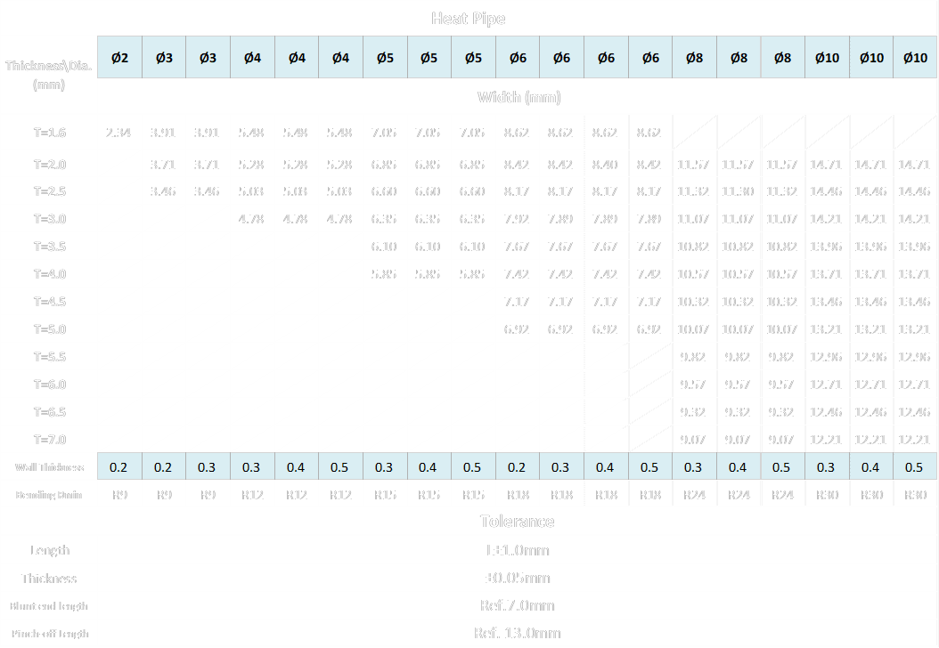
The below chart provides heat pipe specifications and tolerances. Please contact us with any additional questions.
Heat Pipe Performance
Heat pipe carrying capacity (Qmax) is a measure of the amount of heat in watts the device can carry. It is governed, mainly, by the capillary limit of the sintered wick material whose performance can be modified by varying the thickness and/or the porosity/permeability of the wick. However, there is no one ideal wick design. It changes depending on the application requirements.
Celsia’s online Heat Pipe Calculator provides performance information based on two wick designs: standard and performance. However, we regularly design custom wick structures to precisely match customer requirements. These include the ability to vary the wick structure from one portion of the heat pipe to the next. Please contact us if you require performance figures not presented here.
The charts below show output from the heat pipe calculator using the following user-selected parameters:
- Heat Pipe Length: 200mm
- Evaporator Length: 25mm
- Condenser Length: 75mm
- Wick Type: Standard
- Operating Temperature: 60 oC
The first chart shows heat pipe carrying capacity (Qmax) vs Angle of Operation. At +90 degrees the evaporator is directly below the condenser, at –90 the reverse is true.
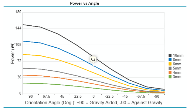
While this chart shows a nearly 90% drop-off in Qmax from +90 to -90 (standard wick), the accompanying table (not shown) gives the precise Qmax by angle. For instance, if the application requires the heat pipe to operate a no less than horizontal (0 degrees), an 8mm heat pipe will carry 62 watts of power from the heat source given the input parameters shown earlier.
The next chart (not shown) and associated table (shown) in the calculator has to do with the change in temperature (delta-T) from one end of the heat pipe to the other. This measurement is not actual length but effective length which is the heat pipe distance from the midpoint of the evaporator to the midpoint of the condenser.
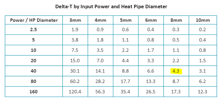
To calculate heat pipe thermal resistance, divide its delta-T by the power input. By choosing an 8 mm heat pipe with input power of 40 oC the thermal resistance is 4.3/40 = 0.11 oC/W. Additionally, the heat pipe calculator provides the thermal conductivity for use as a necessary input to CFD programs like FloTherm. Visit this link for additional information on how to use the heat pipe calculator.
Secondary Operations to Heat Pipe Designs
Before heat pipes are integrated into a heat sink, engineers have several secondary operations to choose from.
Flattening the Heat Pipe
Typically, sintered copper heat pipes can be flattened to a maximum of between 30% to 65% of their original diameter. However, the heat pipe carrying capacity is often negatively affected. The table below shows the Qmax for the most common heat pipe sizes which are round vs flattened. For example, a 3mm heat pipe fattened to 2mm will have heat carrying capacity 30% less even though the pipe has only been flattened by 33%. Compare that to a 6mm heat pipe flattened to 2mm. Its Qmax is reduced by 13% even though it’s 66% flatter.
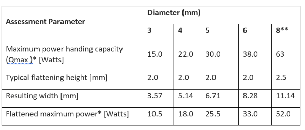
* Horizontal Orientation
** Thicker Wall and Wick Structure
Why does flattening smaller heat pipes have more of a negative effect on Qmax? Simply put, there are two heat pipe performance limits important for terrestrial applications: the wick limit and the vapor limit. The wick limit is the ability of the wick to transport water from the condenser back to the evaporator. As mentioned, the porosity and thickness of the wick can be tuned to specific applications, allowing for changes to Qmax and/or ability to work against gravity. The vapor limit for a particular application is driven by how much space is available for the vapor to move from the evaporator to the condenser. It is the lower of these two limits, for heat pipes that have been designed to meet application requirements, that determines Qmax.
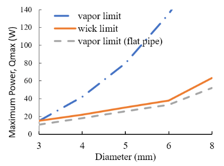
The above chart illustrates this dynamic. The round 3mm heat pipe (blue and orange lines) has vapor and wick limits that are almost identical. Flatting it to 2mm results in the vapor limit below the wick limit. For a 6mm round heat pipe, there is a lot of excess vapor limit so the Qmax won’t be diminished until the pipe is reduced considerably.
Bending Heat Pipes
Bending the heat pipe will also affect the maximum power handling capacity, for which the following rules of thumb should be kept in mind.
- First, minimum bend radius is three times the diameter of the heat pipe.
- Second, every 45 degree bend will reduce Qmax by about 2.5%. From Table 1, an 8 mm heat pipe, when flattened to 2.5mm, has a Qmax of 52 W. Bending it 90 degrees would result in a further 5% reduction. The new Qmax would be 52 – 2.55 = 49.45 W.
Heat Pipe Plating
Nickel plating heat pipes is done to protect against corrosion in situations where the parts are exposed to the environment. It can also be done purely for aesthetic reasons.
Heat Pipe Selection Example
Assume a 20 x 20mm heat source dissipating 70 watts of power with a single 90 degree bend – what are the appropriate heat pipe options?

- To ensure each heat pipe receives the same amount of heat, place them directly above the heat source, or very nearly so. This can be done with three round 6mm heat pipes or two flattened 8mm heat pipes (flattened to 2.5mm).
- Make sure each pipe can handle the heat load of 70 watts. Three 6mm heat pipes can carry 38 watts each = 114 watts, while the two 8mm flat can carry a total of 104 watts.
- Derate the heat pipe carrying capacity by 25% (good design practice). The derated 6mm option can carry 85.5 total watts what the 8mm option can carry 78 watts.
- Account for bending by derating 2.5% fo the 45 degree bend. Here we have a 90 degree bend so the two options can carry 81W and 74W respectively.
As can be seen from this analysis, both heat pipe configurations are adequate to transport heat from the evaporator to the condenser. So why choose one over the other? From a mechanical perspective it may simply come down to heat sink stack height at the evaporator, i.e. the 8 mm configuration has a lower profile than does the 6mm configuration. Conversely, condenser efficiency may be improved by having heat input in three locations versus two locations, necessitating the use of the 6 mm configuration.
Heat Pipe Design Guidance for Heat Sink Integration
Once the correct heat pipe(s) have been identified the next step is integration into the heat sink. When heat pipes are used to move heat (vs spread heat) this is a two-step process: heat sink integration at the evaporator and heat sink integration at the condenser.
Interface Between Heat Pipe and Heat Source (Evaporator)
There are two often used methods for connecting heat pipes with the evaporator: indirect and direct.
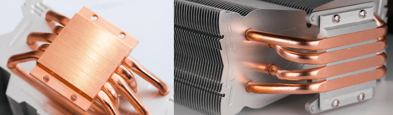
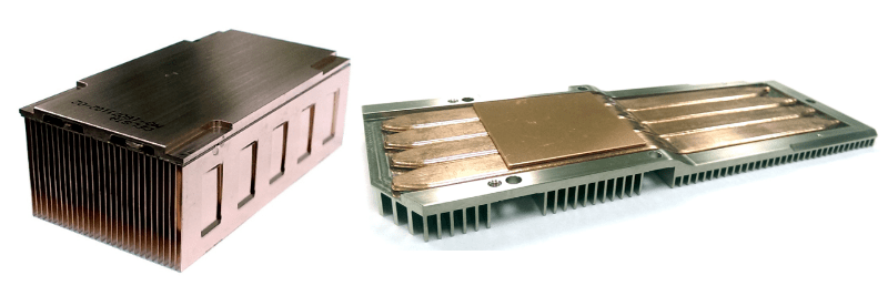
The more cost effective method of mating heat pipes to a heat source is usually through a base plate. This can be done with either an aluminum or copper plate (shown on left). In addition to cost advantages, this method also allows heat to be distributed more evenly to each heat pipe in situations where the heat source is much smaller that the heat pipe contact area.
Direct interface from the evaporator to the heat pipes is usually reserved for situations where the base plate and associated additional TIM layer needs to be removed for performance reasons as shown in the image to the left. This comes with cost implications as the face of the heat pipes needs to be machined in order to make the needed thermal connection with the heat source.
Interface Between Heat Pipe and Fin Stack (Condenser)
The last step is properly integrating the heat pipe(s) into the condenser portion of the heat sink. It a situation where heat pipes are being used to spread heat to a local heat sink (image below left) flattened heat pipes are soldered to the base of the heat sink
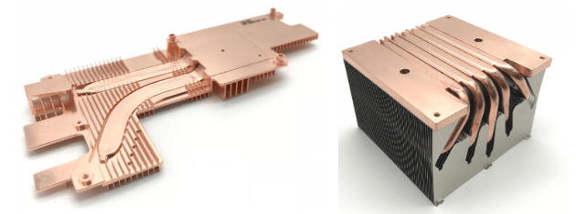
When moving heat to a remote condenser, there are two common heat pipe mounting configurations. The first is identical to the method above. Namely, flattened heat pipes are soldered to a flat base or round heat pipes soldered to a grooved base. If the fin stack is large, heat will need to be distributed more evenly by running the heat pipes through the center of the fin stack as seen in the above right image.
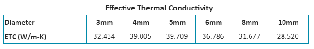
Heat Pipe Modeling Tips
When working in a CFD program like FloTherm or developing an Excel model, there comes a point where you need to input the heat pipe effective thermal conductivity. Here’s how to find these figures using our Heat Pipe Calculator. After entering the required inputs, the first table of the Calculator provided heat pipe effective thermal conductivity figures.
When early in the modeling cycle, there’s a fairly good way to cheat if you don’t have access to this calculator. Simply multiply the power input into each heat pipe by an estimate of its thermal resistance – this will give you the estimated heat pipe delta-T. For heat pipes from 3-8mm use 0.1 oC/W or 0.075 oC/W for larger ones. Then enter in a thermal conductivity figure (start at 4,000 W/m-K and go up) until the modeled delta-T equals the roughly calculated detla-T.
Contact Us with Questions or To Receive a Quote.