
Electronic cooling problems are not always solved the same way. Some designs only require solid metal conduction through aluminum or copper heat sinks. Others reach a point where heat must either spread more efficiently or move farther than conduction alone can support within the available space, weight, or airflow limits. That’s when the vapor chamber vs heat pipe decision comes into play.
The architecture decision usually comes down to three questions:
- How concentrated is the heat source?
- How far does the heat need to move?
- How much thermal resistance can the system tolerate?
Conduction cooling, heat pipes, and vapor chambers each solve different parts of the thermal path.
Solid conduction works well when heat transfer distances are short and thermal loads remain manageable within the available material mass and airflow. Heat pipes are typically used when heat must be transported efficiently to a remote fin stack or chassis wall. Vapor chambers are most effective when heat must first spread away from a localized high heat flux source before reaching the downstream cooling structure.
In many systems, these technologies are used together rather than independently.
Thermal Cooling Architectures
Conduction Cooling
Conduction cooling transfers heat directly through solid materials such as aluminum or copper. This is still the most common thermal architecture in electronics because it is simple, reliable, and cost effective.
Conduction cooling works best when:
- heat transfer distances are short
- heat flux is moderate
- available mass and airflow are sufficient
- thermal spreading resistance is not dominant
As power density increases, solid conduction eventually becomes limited by thermal gradients through the heat sink base and spreading resistance near the heat source.
Copper has a thermal conductivity of roughly 400 W/m·K, while aluminum is approximately 200 W/m·K, but both remain fundamentally limited by solid-state conduction physics.
Applications commonly include:
- conduction cooled chassis
- VPX systems
- industrial electronics
- power supplies
- lower power embedded systems
Heat Pipes
Heat pipes use phase change to transport heat with significantly lower temperature gradient than solid copper alone. They are most commonly used when heat must move efficiently from the source to a physically separate cooling surface.
Heat pipes are generally favored when:
- cooling fins cannot be placed directly over the heat source
- airflow is remote from the device
- transport distance exceeds practical solid conduction capability
- geometry flexibility is required
- thermal transport is the primary limitation
Heat pipes function primarily as thermal transport devices. While flattened heat pipes provide some local spreading capability, they are generally less effective than vapor chambers at managing highly concentrated heat flux across broad planar surfaces.
Applications commonly include:
- remote fin stacks
- chassis conduction paths
- telecom base stations
- embedded computing systems
- aerospace and industrial electronics
Vapor Chambers
Vapor chambers use the same two-phase transport physics as heat pipes, but in a planar geometry optimized for heat spreading.
Rather than primarily transporting heat linearly, vapor chambers redistribute localized heat across a larger surface area before the heat enters the downstream cooling structure. This reduces spreading resistance and improves temperature uniformity at the source interface.
Vapor chambers are commonly evaluated when:
- heat flux is highly concentrated
- z-height is limited
- multiple devices share a common spreader
- spreading resistance dominates junction temperature
- localized thermal gradients limit performance
They are frequently integrated beneath:
- fin stacks
- conduction plates
- embedded heat pipe structures
- high-density electronic assemblies
One-Piece Vapor Chamber Designs
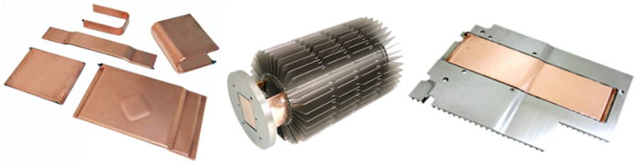
Celsia manufactures one-piece vapor chamber structures derived from a single copper tube rather than a traditional multi-piece welded enclosure.
Like conventional vapor chambers, one-piece designs:
- contact the heat source directly
- support multi-directional heat spreading
- maintain high in-plane thermal conductivity
- tolerate significant clamping pressure at the interface
Because the structure originates from a single formed tube, one-piece vapor chambers can reduce manufacturing complexity relative to traditional welded constructions. These designs also enable certain geometries, including formed or bent profiles, that may be difficult to achieve with conventional two-piece assemblies.
One-piece vapor chambers are commonly evaluated when:
- planar heat spreading is required
- mechanical integration is constrained
- assembly complexity must be reduced
- cost targets are aggressive
- spreading and transport functions must coexist within compact electronics packages
Below are a few examples of one-piece vapor chambers.
When Solid Conduction Stops Being Enough
Most thermal systems begin with aluminum or copper conduction. Performance limitations emerge as:
- heat flux increases
- transport distance grows
- airflow decreases
- allowable mass is reduced
- packaging density increases
Beyond a certain point, adding additional copper no longer reduces junction temperature efficiently because the dominant limitation becomes internal spreading resistance within the material itself.
This is typically where two-phase structures begin providing measurable thermal benefit, and where the vapor chamber vs heat pipe decision begins.
Heat pipes primarily reduce transport resistance.
Vapor chambers primarily reduce spreading resistance.
Direct Contact Heat Pipes vs Vapor Chambers
Direct-contact heat pipe assemblies place flattened heat pipes directly against the heat source rather than using an intermediate baseplate. This can reduce interface resistance and improve transport efficiency compared to indirect-contact assemblies.
However, because each pipe spreads heat only locally, direct-contact heat pipes are generally less effective than vapor chambers when managing highly concentrated heat flux or multiple nearby hotspots.
As source heat flux increases, vapor chambers are often introduced upstream of the heat pipes to improve temperature uniformity before heat enters the transport structure.
These combined architectures are common in:
- high-performance computing
- telecom infrastructure
- aerospace electronics
- industrial power systems
Key Thermal Architecture Considerations
Thermal architecture selection is rarely driven by total power alone. In most electronics systems, the limiting factor is usually a combination of heat flux, packaging constraints, cooling method, and allowable thermal margin.
Heat Flux vs Total Power
In a heat pipe vs vapor chamber comparison, localized heat flux at the device level often determines whether spreading resistance becomes a dominant limitation. Higher heat flux devices generally benefit more from vapor chambers or other planar spreading structures, while lower flux applications may perform well with conduction cooling or conventional heat pipes.
Mechanical Envelope
Available z-height, footprint clearance, and allowable heat sink mass strongly influence the thermal architecture. In many systems, the limiting factor is not thermal performance alone, but whether the cooling solution physically fits within the available mechanical envelope.
Cooling Method
The downstream cooling method strongly influences the thermal architecture. Forced air, chassis conduction, natural convection, and liquid cooling each create different thermal constraints and allowable temperature rise across the system.
Thermal Margin
As thermal margin decreases, spreading resistance and interface losses become increasingly important, particularly in high heat flux designs.
Environmental and Program Requirements
Shock, vibration, orientation sensitivity, altitude, manufacturability, reliability requirements, and program constraints all influence the feasible thermal solution. In aerospace, defense, telecom, and industrial systems, thermal architecture is often driven as much by mechanical integration and long-term reliability as by thermal performance itself.
Thermal Architecture Selection Guidelines
Knowing when to use heat pipes vs vapor chambers, or solid conduction, usually comes down to the dominant thermal bottleneck within the system rather than total power alone.
| Primary Thermal Constraint | Architecture Typically Favored |
|---|---|
| Short conduction path with moderate heat flux | Solid conduction cooling |
| Remote fin stack or chassis wall | Heat pipes |
| Localized hotspot beneath fins | Vapor chamber |
| Tight z-height with high power density | Vapor chamber |
| Large allowable heat sink mass | Solid copper or aluminum conduction |
| Airflow located away from heat source | Heat pipes |
| Spreading resistance dominating junction temperature | Vapor chamber |
| Lowest cost and simplest manufacturing | Conduction cooling |
| Combined spreading and transport limitations | Vapor chamber + heat pipes |
Cost and System-Level Tradeoffs
Conduction cooling generally provides the lowest system cost and simplest manufacturing approach when thermal requirements can be met with solid aluminum or copper heat sinks alone.
Heat pipes are often the most cost-effective two-phase solution when heat must be transported efficiently but spreading resistance is not the dominant limitation. Their mature manufacturing base and geometry flexibility make them common across industrial, telecom, and embedded electronics.
Vapor chambers typically carry a higher component cost than equivalent heat pipe solutions, but the added cost can be justified when:
- heat flux is highly concentrated
- z-height is constrained
- thermal spreading dominates junction temperature
- multiple heat pipes would otherwise be required
- reducing fan speed, system size, or mass offsets thermal hardware cost
In many higher power systems, the architecture decision is driven less by the cost of the two-phase device itself and more by the cost of failing to meet thermal performance within the available mechanical envelope.
Programs often evaluate thermal architecture around:
- allowable junction temperature margin
- package size constraints
- airflow availability
- acoustic limits
- mass limitations
- manufacturability
- long-term reliability
- redesign risk
The thermal solution is ultimately part of the overall system architecture, not an isolated component selection.
Final Design Considerations
No single cooling architecture is universally optimal.
Conduction cooling remains highly effective across many electronics systems. Heat pipes excel at transporting heat efficiently across longer distances. Vapor chambers are most effective when localized spreading resistance limits performance within constrained mechanical envelopes.
When weighing vapor chamber cooling vs heat pipe transport, the key is understanding where the thermal bottleneck actually exists within the system:
- heat transport
- heat spreading
- airflow
- interface resistance
- available surface area
- or mechanical packaging constraints
In many advanced thermal systems, the final architecture combines multiple approaches together to balance performance, manufacturability, reliability, and cost within the realities of the program requirements.