Heat Pipes & Vapor Chambers – What’s the Difference?

Heat Pipes & Vapor Chambers – What’s the Difference?


Most thermal engineers are going to need a two-phase heat sink using either heat pipes or vapor chambers on numerous projects with which they are involved.  Reasons include: 

  • Keep out zones that prohibit a larger heat sink (thicker base, added fin area, etc.) 
  • Enclosure size and/or airflow can’t be increased. 
  • Transitioning to a solid copper heat sink, in whole or in part, adds too much weight and in some cases too much cost. 
  • Component power /density necessitates heat be moved to a remote location more than 40-50mm away from the heat source. 

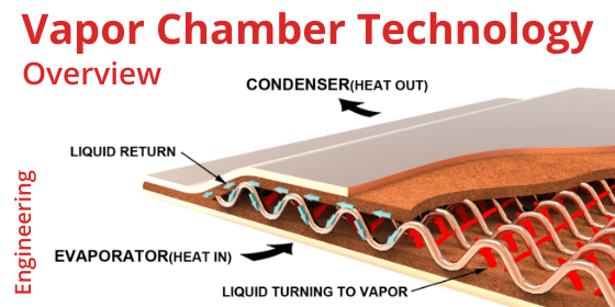
In today’s blog we’d like to do a topline overview of structural differences and thermal design considerations between these very similar yet somewhat unique two-phase devices. If you need some background on the working principles of two-phase devices, please see our article “How do Heat Pipes Work”. 

Structural Design & Cost

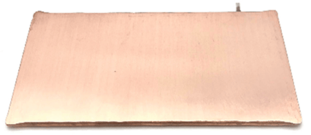
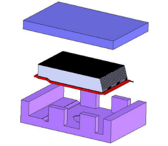
Heat pipes and vapor chambers are composed of the same materials. The most combination is a copper enclosure with a sintered copper wick material. The devices have a small amount of water added and are evacuated to create a partial vacuum. Vapor chambers have an additional support structure (spacer) added for structural integrity and to allow vapor to flow freely. 

Difference between heat pipes and vapor chambers

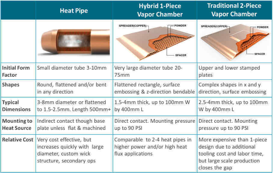
Unlike heat pipes, which have a width to height aspect ratio on the order of 4:1, vapor chambers can have aspect ratios of 60:1 or more. Additionally, vapor chambers can be divided into two categories: a traditional vapor chamber with two stamped plates forming the upper and lower enclosure and a lower cost hybrid 1-piece vapor chamber that begins the manufacturing process as a very large heat pipe. 

Thermal Design Considerations

Heat Pipes

For decades, heat pipes have been the default two-phase device of choice for thermal engineers due largely to the cost delta relative to vapor chambers. They were used both for heat transport, for which they still have an advantage, and for heat spreading, typically using multiple pipes near one another. For lower power applications, perhaps requiring only a single, small heat pipe, or those where heat must be effectively transported, heat pipes keep dominance over vapor chambers due to their low cost and design flexibility. 

Heat pipes cooling notebook pc

Heat Pipes Cooling Notebook Computer (Wikipedia)


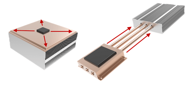
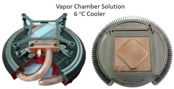
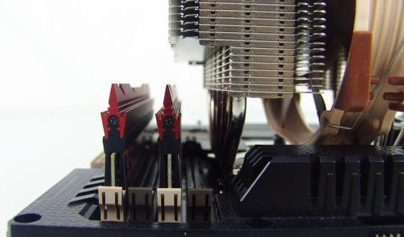
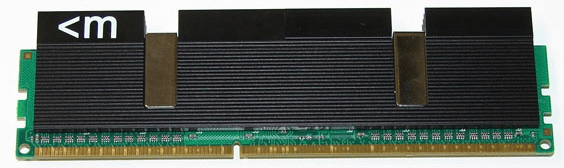
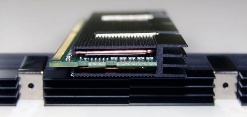
Greater total power and power densities eventually led to heat sinks using multiple heat pipes to solve the thermal challenge. Both images below are heat pipe heat sinks for a small form factor, high performance desktop PC. The one on the left uses a copper base plate in between the heat source and the heat pipes, as is common with heat pipe applications (indirect contact). As processor heat increased in the later generation of this product, the company encountered thermal issues, but did not want to radically redesign the thermal solution as can be seen on the image to the right. Here a vapor chamber replaced the copper base plate, spreading heat more evenly across the heat source and transferring it more effectively to the heat pipes. This is a notable example of how both types of two-phase devices can be used together. 

Heatsink using heat pipes and vapor chamber

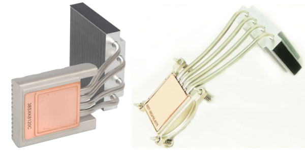
Heat Pipe Heat Sink – (L) Using Solid Copper Baseplate, (R) Using Vapor Chamber (ixbtlabs.com & Celsia)


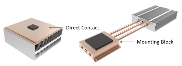
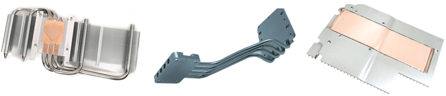
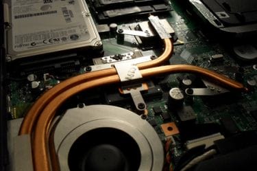
A potential alternative to this problem might have been to implement ‘direct contact’ heat pipes. But this solution has its drawbacks as well. As seen below, this design choice uses slightly flattened and machined heat pipes embedded in an aluminum mounting bracket to make direct contact with the heat source. While eliminating the base plate and added TIM layer – decreasing thermal resistance – it doesn’t spread the heat as effectively as a vapor chamber heat sink solution. 

Heat sink with flat heat pipes

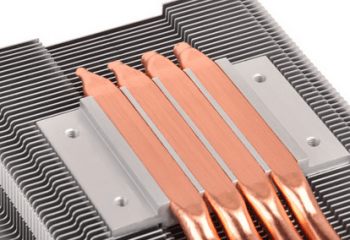
Direct Contact Heat Pipes (Silverstonetek)


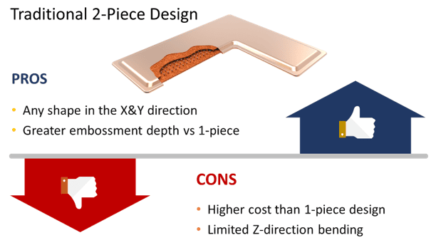
Traditional (2-Piece) Vapor Chamber

Most manufacturers of vapor chambers use a traditional two-piece design.  Studies and practical applications show that the performance of heat sinks using vapor chambers can be enhanced by 20-30% over their heat pipe counterparts. A two-piece vapor chamber design has cost implications of roughly the same magnitude versus a multiple heat pipe configuration. Nonetheless, vapor chamber usage has grown with increasing total powers, higher power densities, and space constraints of today’s devices. 

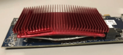
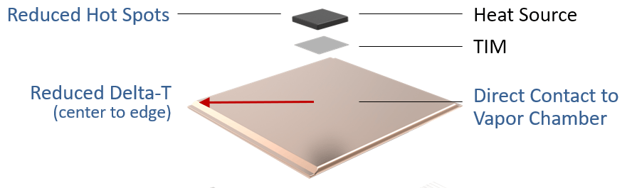
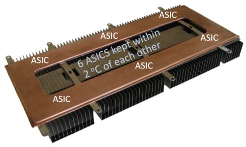
Because vapor chambers do an incredible job of spreading heat, allow for low-profile heat sinks, can be made into virtually any shape, embossed, and make direct contact with one or multiple heat sources, these devices are used in a wide variety of higher power applications. Below are two examples of heat sinks using two-piece vapor chambers. 

vapor chamber heat sinks

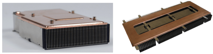
Traditional Two-Piece Vapor Chamber (anandtech.com & Celsia)

As mentioned earlier, the increased cost of this design sometimes limits its incorporation into thermal solutions. Another potential drawback is that there’s little design flexibility in the z-direction. Making a U-shape for instance, while conceivably possible, would be impractical from a manufacturability/cost perspective. 

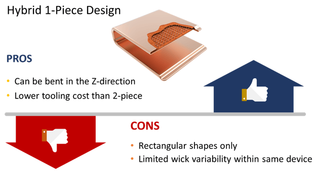
Hybrid (1-Piece) Vapor Chamber

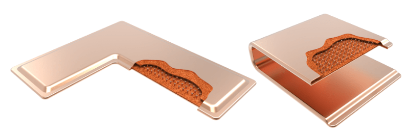
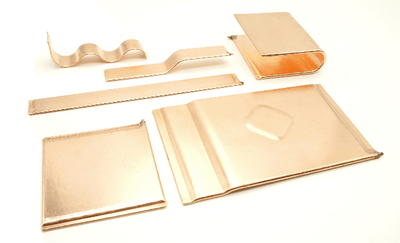
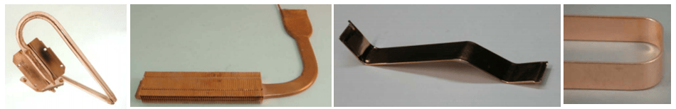
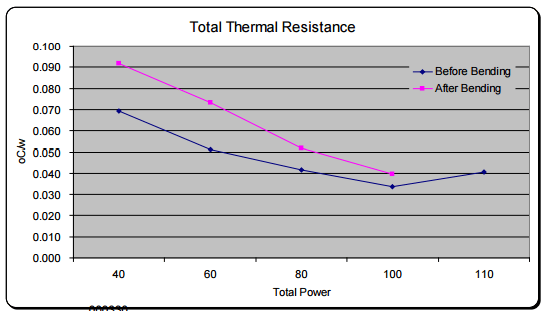
One-piece vapor chambers are a cost-reduced version of their two-piece counterparts yet keep the thermal performance characteristics while adding some unique capabilities (e.g., U-shape bending). Like heat pipes, a one-piece vapor chamber begins its life as a single copper tube, hence the 1-piece moniker. Like traditional two-piece vapor chambers, one-piece vapor chambers make direct contact with the heat source, have a multi-directional heat flow, and can support clamping forces of up to 90 PSI. But they’re less expensive to produce because they need less tooling, don’t use individual support posts, and don’t have to be welded on all four sides. Below are a few examples of one-piece vapor chambers. 

Inexpensive vapor chamber heat sinks

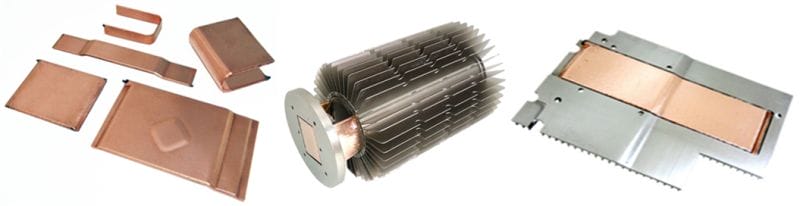
Hybrid One-Piece Vapor Chambers


The thing to remember about two-phase devices is that heat pipes favor moving heat over spreading it, while the reverse is true of vapor chambers. There are many thermal challenges where either could be used with satisfactory results so it’s important to do a thorough review process of both designs before settling on one. 

Please contact us, if you’d like to learn more about how Celsia can help with your next heat sink project. We’ve worked on everything from consumer devices to industrial test equipment that require heat sinks to cool anywhere from a few watts to a few kilowatts.

Vapor Chamber Cooling Design Guide

Vapor Chamber Cooling Design Guide

Vapor Chamber Cooling Design Guide


Electronics cooling using a vapor chamber is a fairly common design choice. This vapor chamber design guide is for the most prevalent types of applications: CPU/ASIC to amplifier applications with power ranging from around 20-250 watts, power density greater than 20 W/cm2, and heat source sizes of between 10-30mm square.  The focus is on vapor chamber cooling using a copper envelope with sintered copper wick and water as the working fluid. The following topics are covered in this guide.

  1. Vapor Chamber Cooling Design Parameters
  2. Vapor Chamber vs Heat Pipe
  3. Types of Vapor Chamber Design
  4. Vapor Chamber Usage Guide
  5. Vapor Chamber Thermal Conductivity & Performance
  6. Vapor Chamber Heat Sink Integration
  7. Dimensional Design Limits of Vapor Chambers


Vapor Chamber Cooling | Design Parameters

Cooling electronics using vapor chambers are subject to the following guidelines:

Power Handling Capacity

Vapor chambers can have the same power handling capacity as multiple heat pipes; from a few watts to over a kilowatt. However, if one heat pipe can meet thermal and physical requirements, it’s probably cheaper to use them – depending on post-production operations like machining. That’s why a move to vapor chambers from heat pipes usually involves applications with higher power and/or higher power densities. Anything less and heat pipes may suffice.

Power Density Capacity

Vapor chambers are particularly well suited for electronics cooling applications where power density is high – roughly above 20 W/cm2 yet below 500 W/cm2. In these situations, it’s usually critical that heat is spread quickly to a larger surface area.

Shapes & Dimensions

The traditional method for producing vapor chambers begins with two stamped plates, mirror images of each other, that eventually get diffusion bonded together. This gives the designer enormous leeway in the X and Y dimensions. Length and width max dimensions are governed by press and furnace size as well as application requirements. Consequently, you typically don’t find vapor chambers in excess of around 300 x 400mm.

Traditional Vapor Chamber | 1-Piece Bendable Vapor Chamber


A few manufacturers also have the capability to produce vapor chambers that start as a very large copper tube (25-70 mm diameter) which is sintered, flattened, and has an internal support structure added to it. We call these 1-piece vapor chambers. The main advantages are cost and the ability to be shaped into L and U configuration. The drawback is they can only be produced in rectangular shapes. Dimensional limits due to manufacturing capability for these typically range in the 100mm wide to 300mm length.

Both types of vapor chambers, particularly when designed with a sintered wick structure, are between 2.5-4mm thick depending on the power to be moved or spread.


Bending

Two-piece vapor chambers made of two stamped plates are generally not bent post stamping. Any small ‘steps’ or bends are done as part of the stamping process. However, one-piece vapor chambers that start as a tube are bend post-production in the factory.  While band radius changes somewhat depending on vapor chamber width, thickness and location of the bend, a typical bend radius is on the order of 7mm for smaller vapor chambers to 12mm for large ones. For more information, see the last section of this article: vapor chamber dimensional design limits.


Vapor Chamber Shapes


Surface Flatness

Vapor chamber surface flatness is particularly important because, unlike heat pipes, they are designed to make direct contact with the heat source. Flatness is controlled in the component contact areas to a nominal flatness is .002”/1” but post-machining, while adding cost, can bring this down to 0.001”/1”. This is typically only necessary when mating to higher power density components with similar flatness for very thin bond line thickness and low interface resistances.


Machined Vapor Chamber


Resistance to Heat Loads

Without modifications, vapor chambers can withstand deformation to around 110 oC. For a copper water vapor chamber to handle higher temperatures, the wall thickness needs to be increased, additional internal support structures are added, and/or an exoskeleton (metal plate) is used on one side of the vapor chamber (the other side is supported by the base of the heat sink). For comparison, heat pipes with their inherently stronger geometry can handle upwards to 200 oC.


Warped Vapor Chamber Caused by Excess Heat Load


Clamping Pressure

Vapor chambers are hollow and require internal support to withstand clamping pressures. Standard designs use supports for up to 60psi of pressure before becoming deformed. However, they can be altered to support up to 90psi.

Surface Treatment

All copper parts are passivated to protect against short term discoloration. Nickel plating is the most common coating used for both heat pipes and vapor chambers for corrosion protection or cosmetic reasons.


Vapor Chamber vs Heat Pipe

Vapor chambers differ from heat pipes in several ways. First, they are more isothermal than either solid metal or heat pipe based solutions. This allows a more uniform temperature across the die face (reduced hot spots) as well a more uniform temperature across the entire face of the vapor chamber (lower delta-T).


Benefits of using a vapor chamber vs heat pipes

Advantages of Vapor Chamber vs Heat Pipe

Second, heat sinks using a vapor chamber allow direct contact between the heat source and the device, reducing interface thermal resistance. Heat pipe solutions usually require an additional base plate and TIM layer.

Third, height constrained thermal solutions often benefit from vapor chambers because they a) make for a thinner base to which the fin stack is attached and/or b) allow for more fin area as heat pipes typically go through the center of the fin stack.


Types of Vapor Chambers

While everyone is familiar with a traditional vapor chamber that’s made from two stamped pieces of metal (2-piece design), there’s another method for producing these devices that offers some unique advantages.

For shapes other than a rectangle, a 2-piece vapor chamber is needed because the stamped plates can be created in virtually any shape along the XY planes. Additionally, they’re able to have a higher embossment should the heat source be recessed. Unfortunately, they come at a slight cost premium over a 1-piece and cannot be bent post-production


Pros and Cons of Traditional Vapor Chamber


A handful of manufacturers are now producing a 1-piece vapor chamber – so named because it begins life as a very large single copper tube which is flattened and has a corrugated spacer inserted for structural purposes. While its shape is limited to a rectangle, it can be bend in the Z-direction forming steps, L-shapes or U-shapes.


Pros & Cons of 1-Piece Vapor Chambers


Vapor Chamber Usage Guidelines

Use a vapor chamber when the heat sink design is conduction limited and here are a few simple rules, followed by some links to online calculators, that will help determine if a vapor chamber is a good solution. Here are some simple rules of thumb to remember:

Use Vapor Chambers When the Thermal Budget is Tight

The thermal budget is simply the maximum ambient temperature at which the end product will operate minus the maximum temperature of the component Tcase. For many outdoor or rugged applications, thermal budgets can be well below 40oC.

Vapor chambers should be used when the thermal budget is tight

Sum of the Delta-Ts Must be Below the Thermal Budget

That means that the sum of all individual delta-Ts (from TIM to Air) must be lower than the calculated thermal budget.  For typical applications in this category, we generally need the delta-T of the heat sink base to be 10oC or less. Visit our online calculator to see the difference in heat sink delta-Ts for your application.

Use Celsia’s online heat sink calculators to help determine if a vapor chamber should be used in place of an aluminum or copper base.


When the Ratio of Vapor Chamber to Evaporator Area is >10:1

Like heat pipes, vapor chamber thermal conductivity increases with length. This means that a vapor chamber the same size as the heat source will offer little advantage over a solid piece of copper. A good rule of thumb says that the area of the vapor chamber should be equal to or greater than 10X the area of the heat source.  In situations where the thermal budget is large or when a lot of airflow drives a small fin stack this may not be an issue. However, it’s often the case that the base of the sink needs to be considerably larger than the heat source.

As this Ratio is Reduced, Solid Copper Becomes an Option


Use a Vapor Chamber When the Primary Goal is to Spread Heat

While vapor chambers can sometimes be used to move heat to a remote heat sink, we most often see vapor chambers used to spread heat to a local heat sink. Heat pipes are ideal for connecting the heat source to a remote fin stack especially as this often involves a series of twists and turns.


Typical usage scenario for vapor chamber and heat pipes

Vapor Chambers Spread Heat | Heat Pipes Move Heat


Vapor Chamber Thermal Conductivity & Performance

When looking at the effective thermal conductivities of heat pipes and vapor chambers it appears that vapor chambers have lower thermal resistances than heat pipes do. This is due to the substantial cross-sectional area that vapor chambers have when compared to typical heat pipes. The average 6mm heat pipe has a cross-section of 28mm2 while even a small vapor chamber, 3mm x 40mm, has a cross-section of 120mm2 (dT = Q*L/(k*A).

If transporting the same power then the effective thermal conductivity goes down by the ratio of the cross-sections. A key point to remember is that although the VC has a lower effective conductivity, they offer performance advantages such as higher total capacities, better operation against gravity, direct contact to the heat source and somewhat lower delta-ts.


Vapor Chamber Heat Sink Integration

Vapor chambers can be attached to any kind of heat sink (extruded, skived, etc) but most often they are paired with zipper fins, also known as fin packs, or machined heat sinks.  There are two reasons for this. First, both of these heat sinks have very good thermal performance; zipper fins due to the ability to have very thin, closely spaced fins, and machined due to virtually infinite geometrical design options. Sometimes we see them successfully paired with die-cast housings with integrated fins used in extreme environments.


From Left: Zipper Fin Heat Sink, Machined Heat Sink, Die-Cast Heat Sink


Regardless of heat sink type, vapor chambers must be attached to the base/fins. They are soldered (most common) or epoxied to the base of the fin stack, the former having better thermal conductivity. Solders used for these assemblies have thermal conductivities on the order of 20 to 50 W/mK while epoxies are on the order of 1/10th of solder conductivities which makes them only useful for low power density applications <10 W/cm2.


Solder Thermal Conductivity & Melt Temperature

Solder Thermal Conductivity & Melt Temperature


Soldering takes place at temperatures generally above the max temp for vapor chambers so special care must be taken in designing solder fixtures. These fixtures must be able to withstand the internal pressures generated in the vapor chamber during the soldering process to prevent vapor chamber deformation. The pressure chart below indicates the internal vapor chamber pressures vs temperature.


Vapor Chamber Temperature Vs. Internal Presure


The solder fixture (shown below in purple) is designed to conform to that of the heat sink assembly, preventing it from deforming during the soldering process. The upper and lower portions are clamped or bolted together to prevent the vapor chamber from expanding.


Solder Fixture (Purple)


Celsia Vapor Chamber Dimensional Design Limits

The table below lists the specifications and tolerances for 1-piece vapor chambers. Because these vapor chambers begin as a very large tube, diameter is listed first followed by widths at various thicknesses as well as tolerances.  No table is provided for 2-piece vapor chambers as they can assume so many configurations although similar tolerances apply. With regard to Celsia’s 2-piece capabilities, 300 x 300mm is the largest possible form factor while sizes of roughly 75 x 150mm are the most common.


Vapor Chamber Specifications

Related Links

Vapor Chamber | Heatpipe Alternative

Vapor Chamber | Heatpipe Alternative

Vapor Chamber | Heatpipe Alternative


A vapor chamber is an effective heatpipe alternative that boosts heat sink performance by  5-10 oC for typical electronics cooling applications. Vapor chambers are a simple, relatively cost-effective, and very dependable device that can be used alone or in combination with heatpipes.

Vapor chambers operate under the same working principles as a heatpipe. They have a metal enclosure which is vacuum-sealed, an internal wick structure attached to the inside walls, and move liquid around the system using capillary action.  Unlike heatpipes, vapor chambers can achieve an impressive 60:1 width to height aspect ratio (flattened heat pipes are on the order of 4:1).

Let’s take a look at the conditions most likely to result in vapor chambers becoming the best solution versus heatpipes or solid metal solutions.

Vapor Chambers When the Thermal Budget is Very Tight

Heatpipes become a likely solution when the thermal budget is less than 40 oC, but as this budget shrinks vapor chambers become the likely hero. The main reason? Vapor chambers make direct contact with the heat source while heatpipes generally have a base plate between them and the heat source.

Note: thermal budget is the difference between the maximum semiconductor temperature (Max Tcase or Tjunction) and the maximum operating ambient temperature of the final system (Max Ambient).

And yes, you are correct that a heat source can make direct contact with a heat pipe solution. Two issues:

  1. The heatpipes have to be fly cut, adding an additional step and expense to the solution.
  2. The mounting block still has solid metal channels between the pipes, reducing thermal performance and possibly creating die face hot spots.

Vapor Chambers When You Need to  “Isothermalize”

Vapor chambers are ideal for applications where high power densities need to be dispersed quickly, hot spots across the die face need to be minimized, or 2+ heat sources are required to be close in temperature.  Below, 6 ASICS were required to remain within 2 oC of each other. The center cutout reduced weight.

When the goal is to achieve as uniform a temperature as possible, vapor chambers trump heatpipes by virtue of their large contiguous surface area that move heat in every direction. Heatpipes only move heat in a linear direction.

Vapor Chambers When Heat Sink Height is Constrained, Yet Fin Area Needs to Grow

Typically, heatpipes run through the center of a fin stack in order to maximize contact area and therefore transfer as much heat to the fins as possible. The downside – fin area is reduced. While this is not a problem if you’ve got the room to increase fin height, it poses a problem when that metric is constrained, as it is here in an add-in desktop graphics card application. A vapor chamber cooling design frees up needed fin area and provided direct contact to the heat source resulting in a 6 degree performance gain.

Vapor Chamber Conclusion

As mentioned in the opening to this article, heat sink performance improvement of 5-10 oC can be had by using a vapor chamber in place of heatpipes because they make direct contact with the heat source, can more evenly distribute heat across a large base, and allow for maximum fin area.

At Celsia, most of the applications for which we design benefit more from heatpipes than a vapor chamber, albeit those with application-driven changes to wick thickness and porosity to boost performance. But, that’s not to say we aren’t deeply invested in vapor chamber technology. The inherent performance benefits of these devices have been known since the 1960’s.

Vapor chamber cost relative to heat pipes, until a decade ago, was prohibitive for all but the most critical applications. Fortunately, the growing use of these devices coupled with innovative manufacturing techniques pioneered by us a decade ago (1-Piece Vapor Chamber) have driven the price down to near parity with 2-4 heat pipes. Below is a brief summary of the pros and cons of both types of vapor chambers, but more detail can be found here.

Related Links

Bending Heat Pipes | How it Affects Vapor Chambers & Heat Pipes

Bending Heat Pipes | How it Affects Vapor Chambers & Heat Pipes

Bending Heat Pipes | How it Affects Vapor Chambers & Heat Pipes


The majority of applications for heat pipes, and to a lesser extent vapor chambers, require these products to be bent. Below are respective examples for high-performance graphics card, semiconductor equipment and networking applications.


Bent Heat Pipes and Vapor Chambers

Figure 1: Heat Sinks Using Bent Two-Phase Devices


But what effect does bending a heat pipe or vapor chamber have on their performance? To answer this, let’s first talk about bend parameters then we’ll move into the meat of it and discuss both evaporator and vapor resistances.

Although smaller bend radii are possible, heat pipe guidelines almost universally put their c/l (centerline) bend radius at 3X the diameter of the heat pipe being bent. In other words, for a 5mm round heat pipe bent into a U shape, the resulting OD would be 35mm.

Bend radius for a 1.5-3.5mm thick vapor chambers are about 10mm. For instance, for a 2mm thick vapor chamber the OD of a 180 degree bend would be 22mm. While these would have to stamped into place for a traditional two-piece vapor chamber, one-piece designs can be bent post production, even into a U-shape.


Figure 2: Bending Examples

Figure 2: Bending Examples


Two areas of thermal resistance in these devices must be closely examined. The first is evaporation resistance which is the deta-t due to conduction through the device wall and wick structure as well as phase change of the working fluid into vapor.

In the vast majority of applications, the evaporation resistance is the dominate resistance; therefore, making these devices somewhat length independent. This means that a two-phase device with a transport distance of 75 mm will have almost the same Tsource -Tsink as one with a 150 mm transport distance. This, in effect, doubles the effective thermal conductivity for the longer devices. For a typical water/copper heat pipe with 0.5mm wall and 0.4mm sintered wick, thermal resistance has a nominal value of about 0.1 oC/w/cm2

Figure 3: Heat Pipe

Figure 3: Heat Pipe


The second is vapor transport resistance which is the temperature loss in the transport region due to pressure drop and condensation delta-t’s. This resistance is typically a function of the power density in the vapor space – nominal power densities are 300-400 w/cm2 with a typical maximum of 800-1,000 w/cm2. The nominal thermal resistance of vapor transport is about 0.01o C/w/cm2. Because of the correlation between cross sectional area of the vapor space and vapor resistance, smaller diameter heat pipes or those that have been flattened increases vapor flow thermal resistance.

So how are these two key resistances affected by bending a two-phase device?

Because the evaporator is almost never placed at the arch of a bent two-phase device, we would expect relatively little to no increase in its nominal value when comparing straight and bend two-phase devices. When testing a 3mm thick U-shaped vapor chamber with a 10mm bend radius we see this to be true. Test data showing the evaporation resistance before and after bending is shown in Figure 4. The results are identical within measurement error.


FIgure 4: Evaporator Resistance

Figure 4: Evaporator Resistance


Now let’s look at vapor transport resistance. Due to the pressure drop induced by bending the vapor chamber, we would expect vapor transport resistance to increase due to an increase in pressure drop, thus decreasing the thermal conductivity of the device. Again, testing supports this claim and is relatively consistent between heat pipes and vapor chambers. Bending a two-phase device 180 degrees increases vapor flow resistance by around 50%.


Figure 5: Vapor Resistance

Figure 5: Vapor Resistance


It’s important to note that while vapor transport resistance is significantly affected by bending, its relative contribution to overall thermal resistance is often small. Remember that for an un-bent part, evaporator resistance is a full order of magnitude greater than that of vapor flow resistance.

So, when we examine the overall thermal resistance, we see that the net effect is between 18-40%. You will also note a decrease in the total power. When relying on capillary pumping in the wick structure to return the fluid the bending affects the pore radius and porosity in the bend region. This has about a 10% effect on the Qmax post bending.


Figure 6: Total Thermal Resistance

Figure 6: Total Thermal Resistance


Given that one should generally design a two-phase device to operate at 70% of its Qmax (we’ll use total power of 70W), we see that the thermal resistance of an un-bent device from 0.047 degrees c/w (3.3 °C) to 0.063 (4.4 °C) for a device with a U-shaped bend. This translates to a delta-T of only 0.9 degrees Celsius.

Based on this we can extrapolate some rules of thumb.

  • Spec a straight heat pipe or vapor chamber with 30% thermal safety margin.
    • Example: A lead load of 70w should use a heat pipe designed with a Qmax of no less than 91w.
  • Add total bend radius of the heat pipe/VC. While not perfect this will get you very close to actual.
    • Example: one 90 degree bend and another 45 degree bend = 135 degrees of bend
  • For each 10 degrees of bend Qmax will decline by .56%.
    • In our example from above: 135 degree total bend divided by 10 multiplied by 0.56% = 7.6% decrease in Qmax.
  • So for our 70 w heat source with two bends totaling 135 degrees we’ll need a heat pipe with a Qmax of 70*(1+(.3+.076)) = 96.3w.

Related Links

Vapor Chamber Cooling FBDIMMs

Vapor Chamber Cooling FBDIMMs

Vapor Chamber Cooling FBDIMMs


In a recent post, I talked about the use of fans and micro-thin heat pipes to cool smartphones. Today, I’d like to take you through a project Celsia tackled a number of years ago; cooling performance DDR3 ‘gamer’ memory modules using ultra-thin vapor chambers. This example should serve to illustrate the design advantages of vapor chambers over heat pipes as well as to comment on how consumer perception affects product success.

Whether it’s the CPU, graphics card or memory modules, PC gamers are notorious for demanding products that push performance limits. What’s better than being able to seamlessly run a taxing application in a higher resolution, fire an extra round of ammunition before your opponent, or having the bragging rights to the coolest looking gaming rig around. Nothing!

Mushkin approached us several years ago about creating a memory module cooler that helped gamers build this kind of machine. For most of us, bare-naked modules are just fine. Gamers’ speed requirements drive them to seek the fastest, most stable components which are then overclocked. The added heat generally requires more robust thermal solutions where every degree counts. In the case of performance memory, the most common solution is a simple aluminum spreader as seen below.

Memory Module with Aluminum Heat Spreader (Source: Kingston)

Memory Module with Aluminum Heat Spreader (Source: Kingston)


Attempting to further cool these modules, many of the top companies added one or more heat pipes. While visually aggressive, these coolers rely on the aluminum side spreaders to transport heat to the two phase device, limiting their thermal transport efficiency. Later models tried to solve this problem using flattened heat pipes that made direct contact with the heat source, although they appreciably increased the overall thickness of the module and didn’t entirely cover each FBDIMM. Moreover, both of these solutions increased the height of the heat sink to the point where they couldn’t be used with larger, more extravagant CPU coolers – memory slots are typically located very close to the CPU.

Heat Pipes for Cooling Performance Memory (Source: Apacer & OCZ)

Heat Pipes for Cooling Performance Memory (Source: Apacer & OCZ)

Performance Memory and CPU Heat Sink

Large CPU Heat Sink with FBDIMMs Installed (Source: overclock.net)


Celsia’s challenge was to design and manufacture a low profile solution (x,y,z dimensions) that increased both heat spreading and dissipation while still allowing the use of any CPU heat sink and the ability to populate every memory slot. Since the mid-2000’s, we had been working on perfecting the thermal efficiency and mass production yield rates of one-piece vapor chambers. These devices differ from heat pipes in that they can be made thinner while still allowing adequate vapor flow. They differ from the traditional two-piece vapor chamber designs due to both lower cost and reduced thickness. In either case, this new solution needed to outperform existing competitive offerings while hitting cost targets.

We modeled and turned around our first prototype within a few weeks. A couple of design tweaks later, we arrived at a solution which used two 1.5mm thick vapor chambers and TIM material sandwiched between ribbed aluminum spreaders with a small vertical fin stack. Mushin attached this heat sinks to their top of the line memory and named them “eVCI Coolers” (enhanced vapor chamber interface – oh those marketing folks). In addition to meeting all the design and performance criteria, it was the first time vapor chambers had been used to cool FBDIMMs.

Celsia Designed Vapor Chamber Memory Cooler

Celsia Designed Vapor Chamber Memory Cooler

Two 1.5mm Vapor Chambers per Module

Two 1.5mm Vapor Chambers per Module


Mushkin tested this heat sink against bare modules, in real-world gaming scenarios, in order to highlight the benefits. The temperature of modules without a heat sink was 43.7 degrees C above ambient while those using eVCI heat sinks measured 22.7 degrees C above ambient. In spite of achieving some really stellar thermal performance figures against many FBDIMM heat sink styles, these modules were not received well by the market. Perhaps because they were thermally cool but not visually cool, gamers opted for a more in-your-face design. Maybe elaborate heat pipe solutions just looked like they’d cool better. Market mysteries! But, it might serve as a lesson to thermal engineers who design for consumers whose devices are viewed as an extension of themselves and who revel in technical achievement as well as visual appeal.

This project is a good example of how ultra-thin vapor chambers can be used in space constrained environments. Power and power densities were low enough in this application to allow for a custom mesh wick to be used while a one-piece vapor chamber design kept the cost down. If you’d like to learn more about how Celsia can help with your next heat sink project, please contact us. We’ve worked on everything from consumer devices to industrial test equipment that require heat sinks to cool anywhere from a few watts to a few kilowatts.

Related Links