
A thermal interface material (TIM) is the layer placed between a heat-generating component and the heat sink it sits against. In two-phase cooling assemblies, that means between the device and the heat pipe base, vapor chamber, or evaporator that absorbs the heat. Thermal interface materials are not a Celsia product line; they are a design decision engineers make as part of a two-phase cooling assembly.
In well-designed two-phase systems, the TIM layer is often the largest remaining thermal resistance in the heat path, which is why thermal interface material thermal conductivity, bond line thickness, and contact pressure all influence how much performance the heat pipe or vapor chamber actually delivers.
What a TIM Does in a Two-Phase Cooling Assembly
Mechanically, a TIM fills the microscopic roughness and trapped air gaps between two mating surfaces. Even surfaces that look mirror-flat have peaks and valleys at the micron scale, and air sits in the unfilled space. Air has a thermal conductivity of roughly 0.026 W/m·K, which makes it the worst common heat conductor in any electronics assembly. Replacing that air with a higher-conductivity TIM (sometimes listed as “TIM thermal interface material” in vendor catalogs) drops the contact resistance between the two surfaces by an order of magnitude or more.
In a two-phase assembly, the TIM typically sits between the component case and the evaporator end of a heat pipe, the underside of a vapor chamber, or the base plate that carries heat pipes into the fin pack. That position matters. Once heat has crossed the TIM and entered the working fluid, two-phase transport moves it almost isothermally to the condenser. Everything upstream of the vapor space, including the TIM, becomes a disproportionately large share of the remaining temperature budget.
Common Types of Thermal Interface Materials Used with Heat Pipes and Vapor Chambers
Six types of thermal interface materials cover the vast majority of two-phase cooling assemblies. The table summarizes typical bulk thermal conductivity, target bond line, and the situations where each category fits best.
| TIM type | Typical bulk k (W/m·K) | Typical bond line | Where it fits in a two-phase assembly |
| Thermal grease / paste | ~2 to 12 typical (specialty metal-filled higher) | 25 to 125 µm | Most common between component and vapor chamber or heat pipe base when surfaces are flat and clamping pressure is available |
| Phase change material (PCM) | ~3 to 8 typical | Very thin once melted | Drop-in replacement for grease when production wants pad-like handling with grease-like performance |
| Thermal pads / gap pads | ~1 to 8 typical | Hundreds of µm to several mm | When stack-up tolerance varies, chips on the same base have different heights, or clamping pressure is low |
| Thermal gap filler (dispensed gel/putty) | ~1 to 7 typical | Hundreds of µm to several mm | Auto-dispensed conformable interface for non-flat or multi-component vapor chamber assemblies |
| Thermal adhesive / epoxy | ~1 to 3 typical | Thin once cured | When mechanical attachment is also required and clamping is not an option |
| Metal TIMs (indium foils, solder, liquid metal) | Indium ~86; solders ~50 to 60; Ga-In liquid metals ~20 to 30 | Thin | High-heat-flux applications, often inside packages (TIM1); solder TIMs achieve the lowest contact resistance via intermetallic bonding; rarely used in customer-facing assemblies |
A few points that do not fit neatly into the table:
Bulk conductivity is not the number that ships. The W/m·K value on a TIM datasheet describes the material, not the joint. Bond line thickness, surface flatness, contact pressure, and pump-out behavior over thermal cycling all change what the joint actually delivers in service. A 5 W/m·K paste applied at 50 µm under firm clamping usually outperforms an 8 W/m·K paste at 150 µm under weak clamping. ASTM D5470 test data helps comparison shopping, but only when the bond line and pressure in the test match the application.
Thermal gap filler is a real category, not a marketing label. Engineers reach for a thermal gap filler when a thin grease bond line is not achievable, for example when a vapor chamber covers several die of different heights, or when assembly stack-up tolerances exceed what a 50 µm grease layer can accommodate. Gap fillers trade some thermal performance for mechanical accommodation, and that trade is usually the right call when the alternative is a starved joint or a deformed envelope.
PCM terminology cuts two ways. Phase change material can refer to two different products in thermal design. As a TIM, PCM is a solid wax-like film at room temperature that melts and reflows under heat to fill the joint like a one-shot grease. As a PCM thermal storage device, it is a bulk thermal mass that absorbs energy during the melt and releases it during the freeze. The two share the same physics and almost nothing else in application.
Celsia does not manufacture TIMs. We specify them as part of every custom two-phase cooling assembly we design.
Where TIM Resistance Shows Up in the Thermal Path
The full thermal resistance stack in a typical two-phase heat sink assembly runs from the silicon junction out to ambient air. A simplified version reads: junction-to-case resistance (inside the package), through the TIM, into the heat sink base or vapor chamber lid, across the base spreading region, through the fin attachment, and out to air by forced or natural convection. Our heat sink design fundamentals page covers each layer in more detail, and our thermal resistance fundamentals primer is a useful starting point.
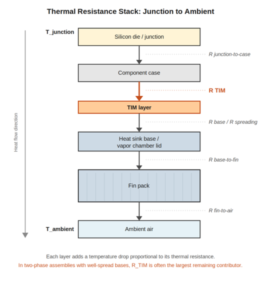
Thermal resistance stack-up diagram showing the layers from silicon junction through TIM, heat sink base, fins, and out to ambient air, with R_TIM highlighted as the focal layer.
R_TIM lands in a specific place in this stack, and its share of the total resistance budget depends on what surrounds it. In a solid aluminum heat sink with mediocre spreading, the base and fin resistances dominate, and the TIM term is one contributor among many. In a well-designed vapor chamber assembly, the base spreading term shrinks dramatically because the chamber spreads heat almost isothermally across its footprint, and R_TIM becomes a proportionally larger share of what remains. Peer-reviewed work on coupled TIM and vapor chamber testing has shown that the interfacial thermal resistance of the TIM can exceed the thermal resistance of the vapor chamber itself (Chen et al., Applied Thermal Engineering, 2023).
This is why thermal impedance, not bulk conductivity, is the more useful number for comparing candidate TIMs. Bulk conductivity (W/m·K) is a material property. Thermal impedance (K·cm²/W or °C·in²/W) is the in-application heat transfer performance at a defined bond line and pressure. ASTM D5470 is the standard test method, and its values translate to real designs only when the test conditions match the assembly conditions. If the application clamps at 50 psi over a 30 µm bond line, lab data taken at 10 psi and 100 µm is not directly comparable.
Why TIM Alone Does Not Fix Spreading Bottlenecks
Engineers often fall into a particular trap: switching to a higher-conductivity grease and finding the design still misses junction temperature targets. A great TIM does nothing to fix a spreading-resistance problem. If heat enters the base over a small footprint and the base cannot move it laterally across the fin pack fast enough, no TIM upgrade will recover the deficit.
Spreading resistance arises when a concentrated heat source dumps power into a comparatively large heat sink base. Conduction through the base material creates a temperature gradient: the area directly under the die runs hot while the rest of the base barely warms. The higher the heat flux at the source, the steeper that gradient becomes.
A 10 mm by 10 mm die dissipating 100 W (100 W/cm²) shows the effect clearly. Our published CFD comparison of identical heat sinks with different bases found that both solid aluminum and solid copper bases exceeded a 35 °C thermal budget, while a vapor chamber base finished at roughly 26 °C delta-T, 5 °C cooler than the next-best heat-pipe option. The spreading term inside the base is what drives those gaps, since the working fluid moves heat across the entire planar area at near-constant temperature. Our high heat flux heat sink design page works through the full comparison with measured numbers.
The practical threshold most thermal engineers use: when delta-T across the base exceeds roughly 10 °C, the design has crossed into spreading-limited territory, and that gradient is invisible to TIM choice. The next step is to model the base spreading resistance directly, not to keep trialing pastes. Our spreading resistance calculator is the fastest way to size the gap.
When to Look Beyond TIM Optimization
Four signs the design has exhausted what TIM choice alone can deliver:
- Swapping from a standard grease to a premium high-conductivity grease produces less than 1 to 2 °C improvement at the junction. The TIM term is no longer the binding constraint.
- Spreading delta-T across the base is large relative to the TIM delta-T. The base architecture, not the TIM, is the next lever.
- The component is a high-heat-flux source (above roughly 50 to 75 W/cm²) sitting on a solid metal base. At these fluxes, copper alone often runs out of conductivity headroom.
- Junction temperature still exceeds the budget with the best practical TIM in place, leaving no margin for end-of-life degradation, pump-out, or worst-case ambient conditions.
When one or more of these signals are present, the next moves are architectural. Options include shifting from aluminum to copper, redesigning the heat sink type to improve fin density or airflow path, increasing forced air, or moving from a solid-metal base to a heat pipe or vapor chamber base. Our heat sink calculator gives a first-pass estimate of whether the existing geometry has any remaining headroom (the usage instructions walk through the inputs).
For modest-flux applications on a tight budget, none of this may be necessary. A copper base with a well-selected TIM can serve a 20 to 40 W/cm² design without trouble. Not every cooling problem needs a vapor chamber. The point is to recognize when a TIM problem is actually a base architecture problem in disguise.
How Vapor Chamber Bases Change the TIM Equation
A vapor chamber does more than spread heat efficiently. It also changes the structural layout of the assembly in a way that directly affects how the TIM behaves. Two points worth being explicit about.
Direct contact eliminates a thermal layer. A heat pipe solution typically uses a metal base plate with embedded heat pipes, which means heat travels from the component through the TIM, into the base, then through a second interface (a TIM, a solder joint, or a press fit) into the heat pipe walls. A vapor chamber sits directly under the heat source. The TIM connects the component case straight to the vapor chamber lid, removing one interface from the stack. Our vapor chamber cooling design guide covers the structural detail of how this works.
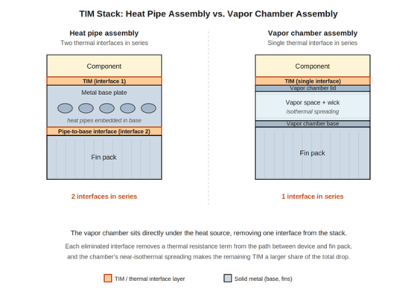
Side-by-side comparison of a heat pipe assembly with two TIM interfaces in series versus a vapor chamber assembly with a single TIM interface.
Isothermal spreading raises the bar for the TIM. Once heat is across the TIM and into the vapor space, the chamber spreads it across the entire base at near-constant temperature. The thermal gradient inside the vapor chamber is small, often a few degrees or less, so the TIM is now an even larger share of the remaining temperature drop between the device case and the fin pack. The same TIM that looked fine on a solid aluminum base may become the dominant resistance term on a vapor chamber base.
The extreme case. For the highest heat fluxes, some designs eliminate the TIM entirely by metallurgically bonding the die directly to a CTE-matched vapor chamber substrate, often aluminum nitride with direct-bond copper. This is not standard practice. It is appropriate for applications above roughly 300 W/cm² where TIM thermal resistance becomes intolerable, and published examples have demonstrated the approach handling 700 W/cm² heat flux. For the vast majority of designs, a well-selected conventional TIM and a well-designed vapor chamber base reach the performance target without that complexity.
Thermal interface material selection is a design decision that interacts with the cooling architecture, and different two-phase architectures make different demands on the TIM.
Design Questions Engineers Should Evaluate
The following checklist captures the questions worth answering before locking in a thermal interface material for a two-phase cooling assembly. Each is one engineers should be able to give a specific answer to during the design review.
- What is the heat flux at the source in W/cm², and what is the total dissipated power?
- What bond line is available? Is the joint flat-to-flat under clamping pressure, or does the geometry require a larger or variable gap?
- What surface flatness and finish are achievable on both the component case and the heat sink mating surface?
- What clamping pressure is mechanically possible at the joint? Pressure affects both grease and PCM performance substantially.
- Does the assembly require electrical isolation between the component and the heat sink?
- What are the maximum and minimum operating temperatures, and how many thermal cycles must the TIM survive without pump-out, dry-out, or delamination?
- Are there outgassing, ITAR, RoHS, REACH, or MIL-STD environmental constraints, particularly for aerospace and defense designs?
- Is the production process compatible with the chosen TIM form factor: automated dispensing, manual application, or pre-applied PCM?
- Has the spreading resistance of the base been calculated? If it is larger than the TIM resistance, optimize the base architecture before optimizing the TIM.
- Has the design been validated with thermal modeling and a measured prototype, not just datasheet math?
Frequently Asked Questions
Does the TIM I choose really matter if I’m using a vapor chamber or heat pipes?
In most cases, yes, and often more than in solid-metal designs. Once a vapor chamber or heat pipe takes over the spreading and lateral transport work, the thermal gradient inside the two-phase device itself is small. The TIM then accounts for a larger share of the remaining temperature drop between the component case and the fin pack. The same TIM that would be acceptable on a heavier aluminum base may be the dominant resistance term once a vapor chamber is doing the spreading.
How thick should the TIM layer be in a two-phase heat sink assembly?
Thinner is almost always better when both surfaces are flat and clamping pressure is available. For grease and PCM with clamped flat surfaces, target the minimum bond line the joint allows in practice, typically 25 to 75 µm. For thermal pads and thermal gap filler materials covering uneven or multi-component stack-ups, the achievable bond line runs from hundreds of µm to several mm, and the assembly accepts the thermal trade in return for mechanical accommodation. Bond line thickness is one of the few TIM parameters engineers can change late in development without redesigning the assembly.
What is the difference between thermal conductivity and thermal impedance on a TIM datasheet?
Bulk thermal interface material thermal conductivity (W/m·K) is a material property measured on a sample. Thermal impedance (K·cm²/W or °C·in²/W) is the in-application heat transfer performance for a defined bond line, pressure, and surface condition. Engineers comparing candidate TIMs for a real design should use thermal impedance, since two pastes with similar bulk conductivities can deliver very different in-application performance when bond line and pressure differ. ASTM D5470 is the standard impedance test method.
Does Celsia manufacture or sell TIMs?
No. Celsia designs and manufactures custom heat sinks and two-phase cooling assemblies. We specify appropriate TIMs as part of every assembly we deliver, but the materials themselves come from third-party suppliers. TIM selection is a design decision, not a product line we sell.
When should I consider a vapor chamber instead of optimizing the TIM further?
When the spreading resistance of the base is the dominant share of the heat sink temperature drop. A practical rule of thumb: if delta-T across a solid metal base exceeds roughly 10 °C, the design has crossed into spreading-limited territory, and TIM optimization stops paying off. The fastest way to check is to calculate the base spreading resistance directly and compare it to the TIM resistance estimate. When the spreading term is larger, vapor chamber evaluation is the next step.