
How Two-Phase Devices Reduce Spreading Resistance Before Heat Reaches the Coolant
Liquid cold plates are widely used in electronic cooling systems because they remove far more total heat than forced-air solutions alone. They are commonly integrated into defense electronics, aerospace systems, telecom infrastructure, industrial power electronics, and compact embedded platforms where thermal loads exceed practical air-cooling limits.
Cold plate cooling is highly effective at removing total system heat. The challenge emerges when large thermal loads are concentrated into a very small source footprint.
As electronic systems become smaller and more power dense, thermal limitations increasingly occur upstream of the coolant channels themselves. Compact processing hardware, RF electronics, conduction-cooled assemblies, and ruggedized embedded systems often generate localized heat flux that conventional cold plate bases struggle to spread efficiently before heat reaches the liquid path.
In many systems, coolant temperature and flow rate are not the primary bottleneck. The dominant limitation becomes thermal spreading resistance between the semiconductor junction and the coolant channels inside the cold plate heat sink.
This is where two-phase devices such as vapor chambers and heat pipes become valuable.
How Liquid Cold Plates Work
A liquid cold plate is a heat exchanger consisting of a metal base with internal coolant channels. Water-glycol, PAO, or dielectric coolant flows through the channels while heat conducts from the electronic assembly into the plate and convects into the moving fluid.
The advantages of cold plate cooling over air cooling include:
- significantly higher heat removal capability
- remote heat rejection through radiators or facility loops
- improved thermal stability at high power
- scalable cooling through flow rate and channel optimization
Cold plates perform well when heat is distributed relatively evenly across a larger surface area, including:
- power conversion systems
- telecom infrastructure
- embedded compute systems
- industrial electronics
- multi-board assemblies
In these architectures, the cold plate primarily removes total system heat.
Why Cold Plates Reach a Thermal Limit at High Heat Flux
The thermal path between the semiconductor junction and the coolant contains multiple resistance layers:
- interface resistance through TIM materials
- spreading resistance through the base structure
- conduction through the cold plate
- convection into the coolant
As source footprint decreases and localized heat flux rises, spreading resistance inside the cold plate base often becomes the dominant limitation.
Heat entering from a small region must spread laterally through the metal base before reaching the coolant channels below. Even aggressive microchannel geometries remain constrained by the conduction path between the semiconductor footprint and the nearest effective fluid boundary.
The result is a common thermal condition:
- coolant temperatures remain acceptable
- flow rates are sufficient
- total system power appears manageable
- but junction temperatures continue rising
Increasing coolant flow can reduce bulk fluid temperature rise, but it does little to reduce spreading resistance within the base itself. Once the spreading path dominates, improving the liquid loop alone produces diminishing returns.
Large localized thermal gradients can also create secondary reliability concerns including TIM degradation, solder fatigue, package warpage, and cyclic mechanical stress.
Why Localized Hotspots Become Difficult to Cool
Localized hotspots are common in compact electronic systems where large amounts of power are concentrated into a small mechanical envelope.
Examples include:
- RF power electronics
- radar processing hardware
- embedded processing systems
- conduction-cooled defense electronics
- compact telecom assemblies
- industrial power conversion hardware
These systems often operate under additional constraints:
- limited airflow
- sealed enclosures
- restricted z-height
- shared cooling infrastructure
- vibration and shock requirements
- SWaP limitations
Engineers often attempt to improve hotspot performance using thicker copper bases, higher coolant flow, microchannel cold plates, or jet impingement cooling. Each approach can improve thermal performance under the right operating conditions, but they also introduce tradeoffs involving weight, pressure drop, pump demand, manufacturing complexity, contamination sensitivity, or mechanical integration.
In many high heat flux systems, improving the thermal spreading path before heat reaches the cold plate is the more practical solution.
Pairing Vapor Chambers and Heat Pipes with Cold Plates
A vapor chamber placed between the heat source and the cold plate spreads concentrated heat before transfer into the liquid cooling structure. Instead of receiving a localized hotspot directly beneath the source, the cold plate condenser sees a broader and more uniform thermal load across a larger surface area.
This allows the cold plate to operate closer to its optimal condition while reducing localized thermal gradients upstream of the coolant channels.
Heat pipes serve a complementary role. While vapor chambers primarily improve localized heat spreading near the source, heat pipes transport heat efficiently to another region of the system where a cold plate or larger heat rejection structure can be located.
This is particularly useful when chassis geometry, EMI shielding, airflow restrictions, or service-access constraints prevent direct placement of the liquid cooling structure above the source.
Machined vapor chambers extend the approach further by functioning as centralized thermal structures that interface with multiple heat sources while coupling into a shared liquid cooling or conduction-cooled assembly.
These architectures are commonly used in:
- defense electronics
- rugged embedded systems
- telecom hardware
- RF power electronics
- aerospace electronics
- compact industrial systems
Celsia’s primary focus is custom two-phase thermal design including vapor chambers, heat pipes, thermosiphons, and integrated thermal assemblies that improve heat spreading and thermal transport within larger electronic cooling systems.
A Common High Heat Flux Thermal Architecture
In many liquid-cooled electronic systems, the primary thermal limitation occurs before heat reaches the coolant channels within the cold plate heat sink.
The architecture below illustrates a common approach used in compact high heat flux electronics:
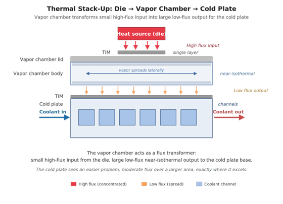
- the vapor chamber spreads concentrated die-level heat laterally
- the cold plate heat sink receives a broader and more uniform thermal load
- coolant channels remove heat under more favorable operating conditions
This approach helps reduce spreading resistance upstream of the condenser while improving temperature uniformity throughout the thermal path.
For applications requiring longer transport distances, embedded or attached heat pipes move heat to a remote condenser section or cold plate heat sink elsewhere in the chassis when direct placement above the source is not mechanically practical.
When to Bring in a Two-Phase Thermal Specialist
A two-phase thermal solution becomes worth evaluating when:
- the cold plate is adequately sized but junction temperatures remain high
- localized spreading resistance limits performance
- flow rate increases provide diminishing improvement
- multiple heat sources share a common liquid cooling structure
- mechanical constraints prevent thicker copper bases
- sealed or conduction-cooled architectures limit airflow access
- SWaP constraints restrict larger liquid cooling hardware
In many systems, the issue is not insufficient liquid cooling capacity. The issue is how efficiently heat reaches the liquid cooling structure in the first place.
Celsia designs custom vapor chambers, heat pipes, thermosiphons, and PCM thermal storage backed by CFD modeling, in-house testing, US engineering support, and Taiwan production. ISO 9001 certified and ITAR registered.
If a liquid cold plate is not closing your thermal budget, request an engineering review.
Frequently Asked Questions About Cold Plates in High Heat Flux Systems
At what heat flux does a liquid cold plate start to struggle on its own?
When local heat flux exceeds about 100 W/cm² and the source footprint is significantly smaller than the cold plate. Below that, a well-designed cold plate handles the load. Above it, spreading resistance in the base typically becomes the dominant share of the resistance budget.
Why doesn’t more coolant flow fix a cold plate hotspot problem?
Flow rate reduces caloric rise and slightly improves the convective coefficient, but it does not change the spreading resistance through the cold plate base. The bottleneck sits upstream of the channels, so flow improvements yield diminishing returns once the base is the limiting term.
When should I use a vapor chamber vs. heat pipes with a cold plate?
Vapor chambers when you need to spread heat directly under the source before it reaches the cold plate. Best for high-flux hotspots and multi-source temperature matching. Heat pipes when you need to transport heat to a cold plate elsewhere in the chassis. Our vapor chamber vs heat pipe comparison covers the trade-offs.
Can a cold plate be designed to handle high flux without a vapor chamber?
Yes, with microchannel, jet impingement, or direct chip contact architectures. Each adds pressure drop, manufacturing complexity, qualification cost, or mechanical risk. For many programs, integrating a vapor chamber upstream of a conventional cold plate is the lower-risk, lower-cost path.