Minimum Bend Radius
As a rule of thumb, the minimum centerline bend radius for heat pipes is three times the diameter. The example below illustrates this calculation for a 5mm heat pipe.

Angle Flexibility
Heat pipes can be bent at any desired angle. Moreover, complex and compound bends can be achieved with relative ease.
Transitioning Between Features
- For consecutive bends, the transition distance between each bend can be zero.
- When flattening sections of the pipe, they should typically be about one-third to one-half of the original diameter.
- When transitioning from a round to flat shape, allow a space approximately equivalent to the heat pipe’s diameter.
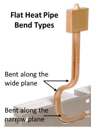
Procedure for Flat Plane Bends
Begin by bending the round heat pipe into the desired shape, then flatten it. This is true for bends along the narrow or wide plane.
Wall Thickness Consideration
It’s possible to have a bend radius smaller than the standard recommendation if the heat pipe’s wall thickness permits. However, be cautious: this may lead to wrinkling inside the bend area, compromising the pipe’s integrity.
Performance Implications
Remember, the performance of heat pipes can be influenced by the number of bent and flat areas introduced. Typically, there’s a performance decrease of around 10% to 15%. Both the maximum heat transport capacity (Qmax) and the ability of the heat pipe to work against gravity will be affected.