A heat pipe is a passive two-phase heat transfer device designed to improve the performance of conventional heat sinks through an evaporation and condensation cycle of a working fluid enclosed within a vacuum sealed enclosure. It operates through the evaporation and condensation of a working fluid within a vacuum-sealed enclosure. Heat pipes are commonly used when standard aluminum or copper heat sinks cannot move or spread heat efficiently from electronic components. Their high thermal conductivity, ability to be bent or flattened, and long operational life make them an excellent solution for directing heat to a remote condenser area, typically a fin stack.
Heat Pipe Technology
To understand heat pipe technology, it is essential to examine its three core components: the enclosure material, wick structure, and working fluid.
Heat Pipe Enclosure / Envelope Material
The enclosure is a vacuum-sealed vessel (tube or envelope) that houses both the working fluid and wick structure. It transports heat away from the semiconductor in vapor form and returns the condensed liquid via the wick. Copper is the most commonly used enclosure material, followed by aluminum, with stainless steel and titanium used in specific applications requiring compatibility and durability. Wall thickness is selected based on structural integrity needs and space constraints.
Heat Pipe Wick Structure
The wick lines the inner wall and is responsible for returning the liquid to the evaporator. Different wick structures offer varying abilities to handle higher power densities and move the working fluid against gravity when the evaporator is above the condenser.
| Power Density | Resistance | Orientation | |
| Sintered Powder | <500w/cm² Good for freeze/thaw and bent shapes Small heat sources up to 1,000w/cm² |
0.15-0.03 °c/w/cm² |
+90° to -90° |
| Screen | <30w/cm² Main use is for very thin heat sinks due to high evaporator resistance. Limited bending. |
0.25-0.15 °c/w/cm² |
+90° to -5° |
| Grooved | <20w/cm² Entry level price/performance must be gravity aided/neutral. |
0.35-0.22 °c/w/cm² |
+90° to 0° |
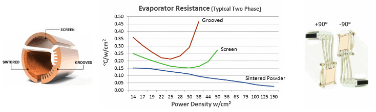
Common Wick Types
Sintered Wick – Formed by fusing powdered copper at high temperatures, similar to brake pad manufacturing. It performs well under high heat flux and against gravity, offering broad design flexibility.
Screen / Mesh or Braided Wick – Made from screen mesh or braided copper strands. Ideal for ultra-thin applications and shallow angles but less effective at higher heat fluxes.
Grooved Wick – Integrated into the extruded pipe structure, offering a low-cost option. Best for gravity-aided or level applications.
Working Fluids Used in Heat Pipes
Phase-change of the working fluid from liquid to vapor and back enables heat pipes to achieve thermal conductivities far higher than solid metal. Fluid choice depends on:
- Fluid Figure of Merit (FOM) – factors in key temperature-dependent variables of liquid: latent heat of vaporization, surface tension, liquid density, and liquid viscosity.
- Min/Max temperature of the liquid during operating and non-operating conditions.
- Safety – usually toxicity or flammability.
- Cost
The figure of merit (FOM), the second column in the table below, is a way to compare how well different liquids perform as working fluids in heat pipes. It’s a score that tells engineers which liquid is better at moving heat around – the higher the figure the better. To calculate the FOM, divide the effective thermal conductivity of the working fluid by its vapor pressure at the operating temperature. Here’s a summary of common heat pipe working fluids:
| Working Fluid | Operating Temperature Range (°c) | Figure of Merit | Surface Tension (mN/m) | Thermal Conductivity (W/mK) | Potential Concerns |
Compatible Enclosures
|
| Water | 0 to 200+ | 140 | 72 | 0.606 | Operation at low temperature |
Copper, nickel, titanium
|
| Ammonia | -50 to 120 | 115 | 28.9 | 0.525 | Toxic, expensive |
Aluminum, stainless steel
|
| Methanol | -40 to 200 | 80 | 22.6 | 0.138 | (Less) toxic, flammable |
Copper, stainless steel
|
| Acetone | -30 to 150 | 70 | 23.2 | 0.163 | Highly flammable, toxic |
Aluminum, stainless steel
|
Once the correct working fluid is selected, a compatible enclosure is selected. Both water and methanol heat pipes are compatible with copper enclosures, while ammonia and acetone heat pipes mainly use aluminum. Mixing incompatible materials shortens the life of the heat pipes.
Heat Pipe Working Principles
Thermal Conductivity – Heat pipe thermal conductivity varies in practical terms between 1,500 to 60,000 W/(mK), unlike solid metals which have a constant value of ~180 W/(mK) for aluminum and ~400 W/(mK) for copper. The reason for the three-fold increase from solid copper to heat pipes at the low end of range is because vapor is an exceeding good heat transfer medium. The reason for the variability, or ‘effective thermal conductivity’, for a given diameter heat pipe is mainly explained by length. Because vapor is so efficient at heat transfer, the difference in temperature between the evaporator and condenser ends of the heat pipe (heat pipe delta-T) is virtually the same for a short heat pipe as it is for a long one, thereby increasing its effective thermal conductivity. See Celsia’s online heat pipe calculator for more precise figures on effective thermal conductivity and heat carrying capacity (Qmax).
Capillary Action – When the evaporator portion of a heat pipe is at or above the condenser area, capillary action provides the mechanism by which the working fluid is able to return to the evaporator from the condenser. This phenomenon uses the inherent surface tension of the working fluid to continuously ‘reach for’ a dryer portion of the wick; a process that can be seen by partially placing a roll of paper towels in a bowl of water.
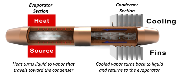
Two-Phase Heat Transfer Cycle – As heat is applied to one end of the heat pipe, some of the liquid working fluid turns to vapor and travels to an area of lower pressure toward the cooling fins. Because the heat pipe is under a partial vacuum, vaporization happens at a temperature much lower than the boiling point at one atmosphere of pressure. At the conder end, the vapor cools and returns to liquid form where it is absorbed by the porous wick structure and transported back to the heat source via capillary action. In a steady state, the process continuously repeats itself.
Operating and Non-Operating Temperatures – the type of working fluid determines the operating range for heat pipes. Water heat pipes operate between 0 oC and 200 oC. Above this temperature, the internal vapor pressure increases, potentially causing structural damage to the heat pipe. Below the rated temperature, the heat pipe may experience wick dry out during start-up. Although freeze/thaw cycles are generally not a problem for sintered wicked heat pipes, start-up below the rated temperature causes the frozen liquid at the evaporator end to melt and turn to vapor – so far so good. However, the cold condenser area of the heat pipe causes the vapor to freeze at the condenser end, eventually drying out the evaporator. Although the IC is at risk of overheating or throttling back, heat pipe operation returns to normal once the ambient temperature is above freezing.
Expected Lifespan – infant mortality is the most common failure point. 100% burn-in testing along with helium leak testing eliminates this issue. Heat pipes that are designed to operate within design parameters, manufactured with quality materials, and whose manufacturing process is in control will last 20 or more years.
Types of Heat Pipes
Constant Conductance Heat Pipes (CCHP) – Standard heat pipes with fixed thermal conductance between evaporator and condenser. Most commonly used.
Other Types:
- Vapor Chambers: Spread heat across a large surface area; ideal for flat baseplates. Include internal supports to maintain vapor space.
- Variable Conductance Heat Pipes (VCHP): Include non-condensable gas to modulate thermal conductance based on ambient conditions.
- Thermosiphons: Rely on gravity; no wick in some cases. Handle higher Qmax than standard devices.
- Loop Heat Pipes: Handle long distances and any orientation; more expensive due to complexity.
- Rotating Heat Pipes: Designed for spinning systems like RF rotary joints; use spiral-grooved wicks.
- Oscillating Heat Pipes: Excel at transferring heat over long distances and against gravity.
When to Use Heat Pipes
Heat pipe technology is ideal when solid metal heat sinks fall short in thermal or mechanical performance.
Key Applications:
- High power density / total power: Reduces delta-T by improving conduction.
- Space-constrained designs: Moves heat to a remote condenser.
- Limited airflow: Improves conduction from the heat source to the fins lowering thermal resistance.
- Weight-sensitive systems: Replaces heavy solid bases with lightweight two-phase options.
Designers must carefully consider shape, mounting method (direct vs. indirect contact), and heat pipe type to optimize performance and cost.
Heat Pipe Performance
More commonly known as Qmax, the maximum heat pipe carrying capacity generally increases with the diameter of the pipe. However, each wick type can be tuned to optimize specific performance parameters and this is especially true of sintered wicks. An online heat pipe calculator and use instructions from Celsia calculates Qmax at different angles of orientation, effective thermal conductivity, and temperature rise (delta-T) for different heat pipe diameters.
For example, the chart below graphs Qmax for typical sintered wick heat pipes of varying diameters against the orientation in which the pipe is required to operate. The grey line represents a10mm pipe designed to maximize Qmax when flat (0-degree orientation). Like all heat pipes the Qmax increases as the evaporator is moved below the condenser. The opposite is also true and there can be as much as a 95% drop in Qmax from one orientation extreme to the next. However, the internal structure – wick thickness, wick porosity, and amount of working fluid – can be changed to optimize for specific conditions.

When the heat pipe is required to operate in orientations between -50 to -90 degrees, the wick structure can be optimized to increase the capillary pumping action. As seen in the chart below, a gravity optimized 6mm heat pipe now has a higher power carrying capacity (Qmax) than its non-optimized 6mm counterpart, to meet the needs of this application. The trade-off? Its Qmax is lower than the non-gravity optimized 6mm pipe in orientations above -45 degrees.

Heat Pipe Bending & Flattening
Heat pipes can be made into virtually any shape by bending and/or flattening them, subject to certain parameters. The typical minimum bend radius is 3-times the diameter of the tube. However, bending a heat pipe reduces its Qmax, the maximum power transport capacity. Smooth, gradual bends have less effect than tight ones, but a good rule of thumb is for every 45-degree bend Qmax will decrease by 2.5%.
Flattening a sintered heat pipe to one-third of its original diameter is generally considered the maximum, although this figure decreases with smaller pipes (2-4mm) and increases with larger ones (>10mm). Ultra-thin heat pipes can be produced using other wick structures. Performance can be affected as the tube is flattened. The chart below offers some insight into how flattening affects heat pipe performance. Provided a heat pipe is properly matched to the application, its Qmax is determined by the lower of the wick limit or the vapor limit. For instance, for a round 6mm standard heat pipe the wick limit (black dotted line) is just under 60 watts. Flattening it to 4, 3.5, or 3mm has no effect on its Qmax as the vapor limit is above the wick limit. Note that flattening a round 8 or 10mm heat pipe to 3mm or 2.5mm will have a substantial effect on its Qmax.

Conclusion
Heat pipe technology delivers unmatched thermal conductivity, shape flexibility, and long-term reliability. It is ideal for electronics requiring high-performance thermal management in compact, complex, or passive environments. Despite a higher initial cost than solid metal alternatives, its performance advantages justify use in applications with high power, space limitations, or severe orientation challenges. Loop heat pipes, vapor chambers, and oscillating heat pipes expand design options for even more demanding requirements.
When designing thermal solutions, engineers must balance operating temperature range, power density, spatial constraints, and mechanical demands. Heat pipe technology offers an efficient and proven method for achieving thermal performance goals across a wide range of industries and applications.