How Do Heat Pipes Work | Heat Pipes 101
How Do Heat Pipes Work | Heat Pipes 101
This article covers how heat pipes and vapor chambers work along with typical uses and configuration options. Further, it is designed to be a quick read with links to detailed information throughout the text.
How Do Heat Pipes Work?
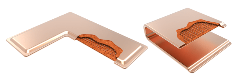
There are three ‘parts’ to a heat pipe that allow it to work: a vacuum sealed enclosure, a wicking structure, and a working fluid. By a large margin, the most common type is a copper enclosure, a sintered copper wick structure that bonds to the interior surface, and de-ionized water as the working fluid. This configuration generally translates to non-space environments with required Max Ambient of less than 80 oC and will be the configuration presented throughout this article.
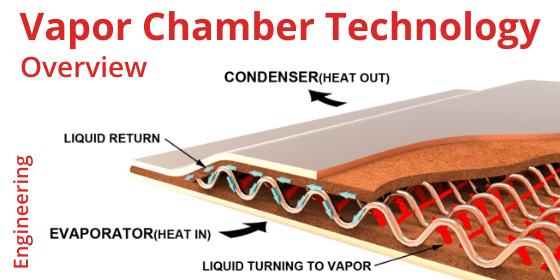
The graphic below illustrates heat pipe working principles. As heat is applied, some of the liquid turns to vapor and travels to an area of lower pressure toward the cooling fins. This allows the vapor to cool and return to liquid form where it is absorbed by the porous wick structure and transported back to the heat source via capillary action – the same principle that will soak the entirety of a paper towel if only one corner is exposed to water.
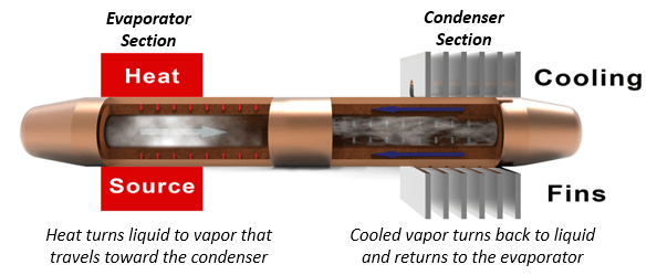
Heat Pipe Working Principles
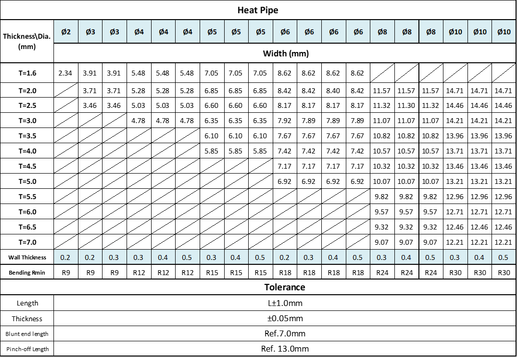
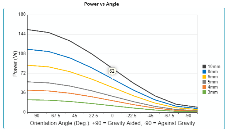
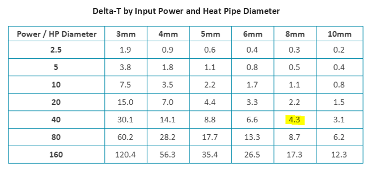
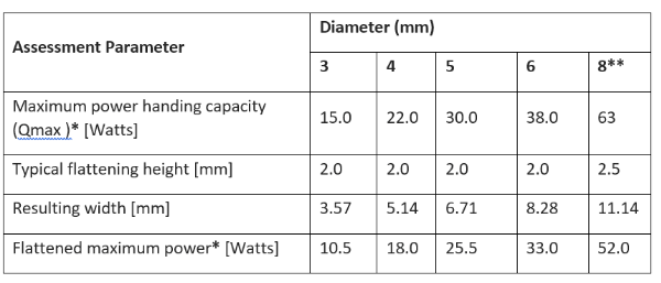
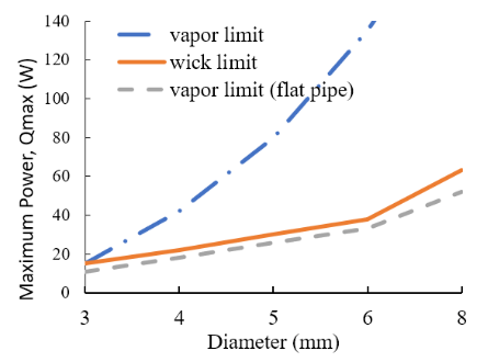
Heat pipes are typically available in sizes from 2-12mm diameter and can be flattened and bent. Moreover, wick properties such as thickness and porosity can be changed to tune thermal performance (Qmax or maximum power carrying capacity in watts). Click here to use the online heat pipe calculator to understand Qmax by pipe size and angle of orientation. A few points:
- Larger diameter heat pipes have higher Qmax.
- Qmax is additive. If one pipe can carry 20W, two can carry 40W and so on.
- Qmax is reduced when the heat pipe is bent, the capillary action is against gravity, required operating altitude above sea level increases, and often when the pipe is flattened (a small amount of flattening typically won’t affect it).
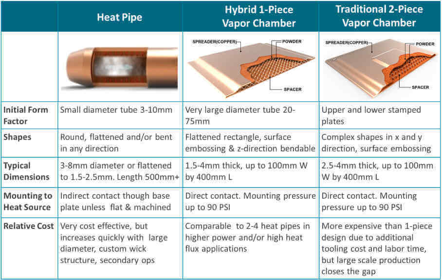
The working principles of vapor chambers are identical to heat pipes. In fact, vapor chambers are often referred to as planar heat pipes. The distinction really comes down to the width to height aspect ratio. A flattened heat pipe typically won’t exceed 4:1, whereas a vapor chamber can go up to around 60:1.
Importance of Heat Pipe Technology
You already know that heat pipes and vapor chambers are two-phase heat transfer devices used to increase the thermal performance of heat sinks that would otherwise use only a solid metal base and fins. But, what drove their mass adoption?
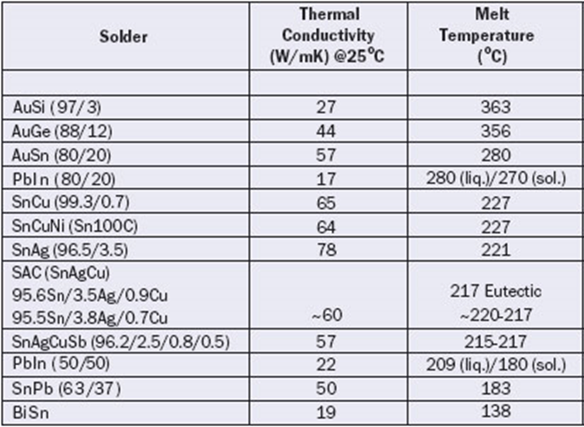
Put simply, heat pipes are widely used because modern electronic components have increased in thermal design power (watts of dissipated heat) and, perhaps more importantly, power density (W/cm2). With these increases, engineers realized they needed to reduce the conduction limits of solid metal. Vapor chambers and heat pipes have, in most cases, dramatically higher thermal conductivities than do solid aluminum or copper. For reference, the thermal conductivity of aluminum is ~200 W/(mK), copper is ~400 W/(mK), and two-phase devices are typically upwards of 6,000 W/(mK) – often dramatically higher.
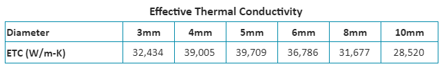
Unlike solid metal, the effective thermal conductivity of two-phase devices changes depending on a host of variables, but mainly with the distance the heat is transferred. The longer the distance, within reason, the higher the thermal conductivity – all else being held constant. See online heat pipe performance calculator for the precise heat pipe thermal conductivity for your application. The chart below illustrates how quickly thermal conductivity increases with heat pipe length.
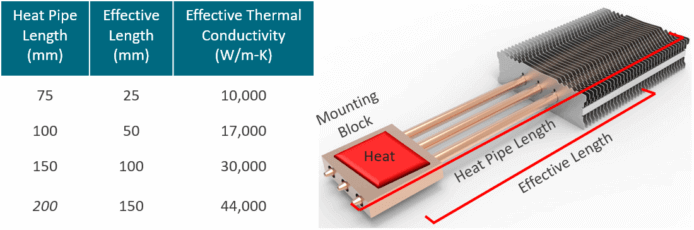
Heat Pipe Effective Thermal Conductivity as Function of Length
Typical Configuration & Uses
Rules of Thumb
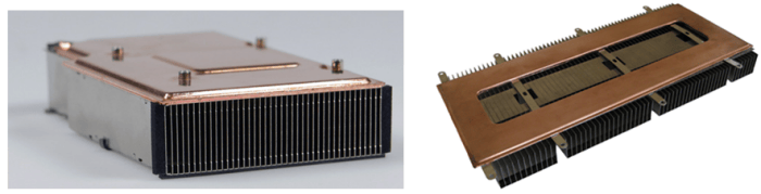
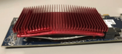
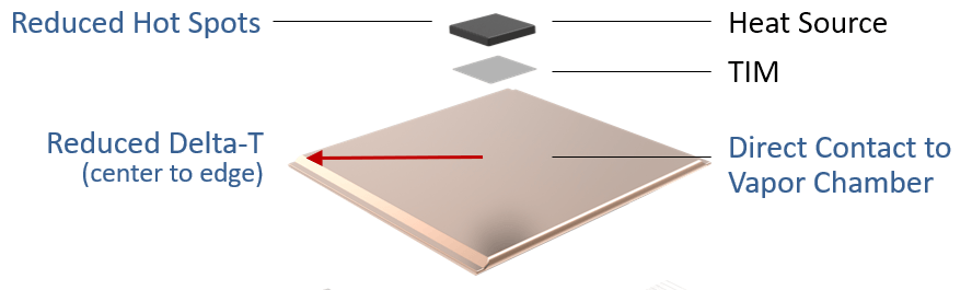
- Use vapor chambers to spread heat across the base of a local fin array (condenser).
- Use heat pipes to move heat to a remote fin array or enclosure wall.
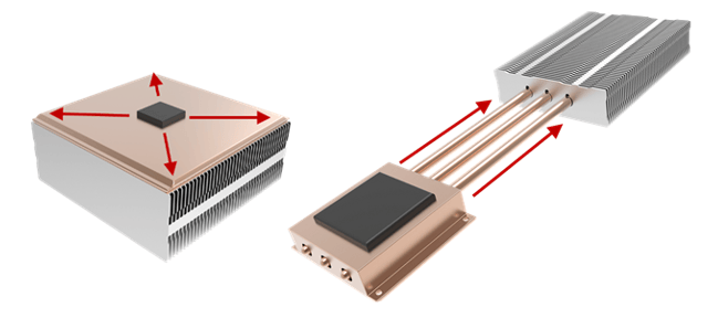
Vapor Chambers Spread Heat | Heat Pipes Move Heat
There are always exceptions, but here are the reasons. Heat pipes can be bent in any direction making them ideal for snaking around PCB components. This makes them well suited for moving heat to a remote condenser which most often requires some maneuvering. Conversely, vapor chambers have a continuous internal vapor space. This allows heat to be distributed in every direction to the remote corners and edges of the fin array, maximizing total fin efficiency.
Telltale Signs You Might Need a Heat Pipe or Vapor Chamber Device
Here’s a list of conditions where two-phase devices might be considered:
- Having to move heat more than 50mm from heat source to remote condenser. Below this, solid copper bar or rods will be almost as effective.
- When the bottom area (base) of a local fin array is greater than 10X the area of the heat source. Remember, lower air flow means larger fin area for a given heat source. This often translates to a larger base footprint as you might not have the vertical space (Z-height) and you certainly won’t have the fin efficiency to increase fin height indefinitely. See our online heat sink size calculator to get a quick estimate of the required heat sink size for your application.
- If a solid copper heat sink (fins and base) meets thermal requirements, but not weight/shock and vibe requirements. A solid copper base is considerably heavier than a comparable vapor chamber base. Additionally, using a two-phase base may allow the use of aluminum fins, further reducing weight.
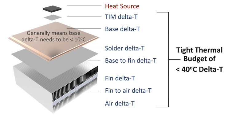
- When thermal budgets are below 40 oC, especially when that’s coupled with low/no airflow. To calculate thermal budget, subtract the max operating temperature at which the finished device is designed to operate (Max Ambient) from the max case temperature (Tcase) of the IC – or junction temperature for bare die ICs (Tjunction). This second figure will be provided by the IC manufacturer. You can use our online heat sink calculator to determine the total delta-T of your heat sink and compare that to your thermal budget.
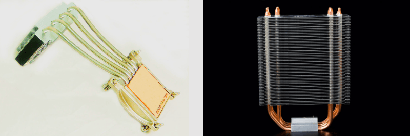
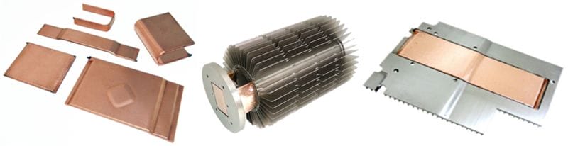
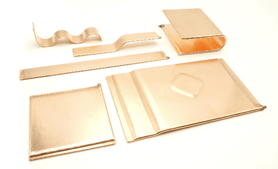
Types of Heat Sinks Used with Two-Phase Devices
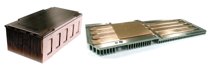
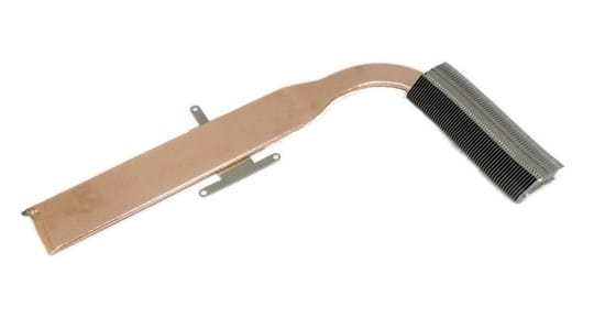
Lower Unit Cost – Extruded heat sinks are the most cost effective but have limited design flexibility. Die cast heat sinks are generally used as the enclosure lid with the fins exposed to the environment but high up-front tooling cost limits these to higher-volume applications.
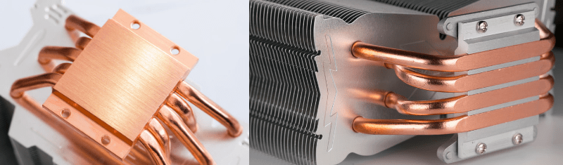
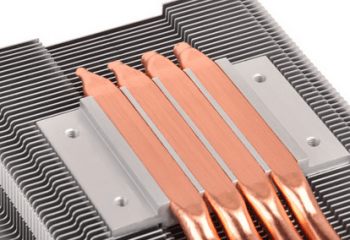
Unique Fin Requirements – Thermal engineers sometimes need heat sinks with either very tall fins or very thin fins that are tightly spaced. Respectively, bonded fin heat sinks and skived fin heat sinks suit these requirements nicely. An advantage of bonded fin designs is that the heat sink base and the fins can be of different metals.
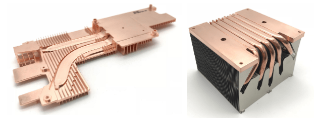
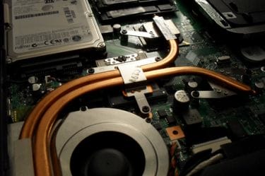
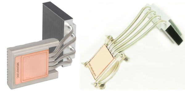
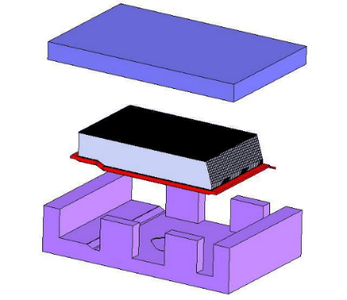
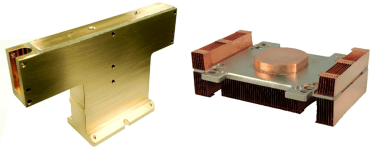
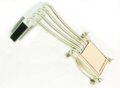
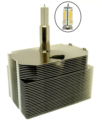
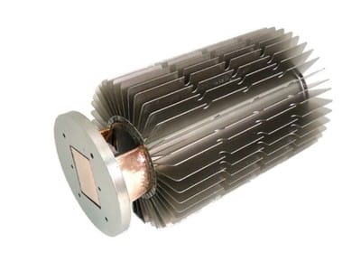
Most Used – What you’ll see most often paired with heat pipe or vapor chamber designs are zipper fins (also called fin packs). They are low weight and can achieve a very high fin density. Vapor chambers can be soldered to the bottom of these or heat pipes can be run through the center of the fins. For low volume, very complicated designs where performance matters, machined heat sinks are the usual solution.
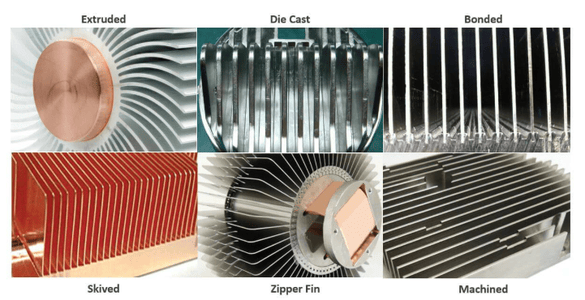
Types of Heat Sinks Used with Vapor Chambers & Heat Pipes
Related Links