Two-phase cooling uses the evaporation and condensation of a working fluid to spread and transport heat with low temperature rise — used when heat is too concentrated, too far from the rejection point, or too constrained by geometry for conduction or conventional cooling approaches alone.
Two-phase cooling uses the evaporation and condensation of a working fluid to spread and transport heat with low temperature rise. It is used when heat is too concentrated, too far from the rejection point, or too constrained by geometry for conduction or conventional cooling approaches alone.
In electronics cooling, two-phase devices such as heat pipes, vapor chambers, and thermosyphons are typically used between the heat source and the final heat rejection method. They move heat to where it can be rejected more effectively — through a heat sink, cold plate, chassis, airflow path, or liquid loop.
HEAT PIPES
VAPOR CHAMBERS
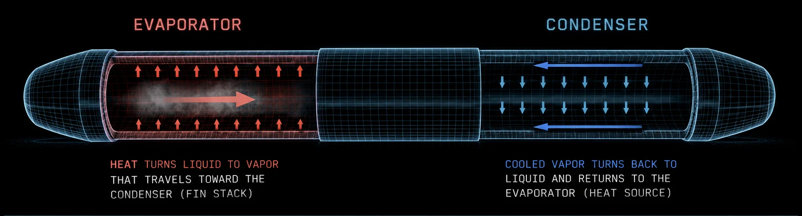
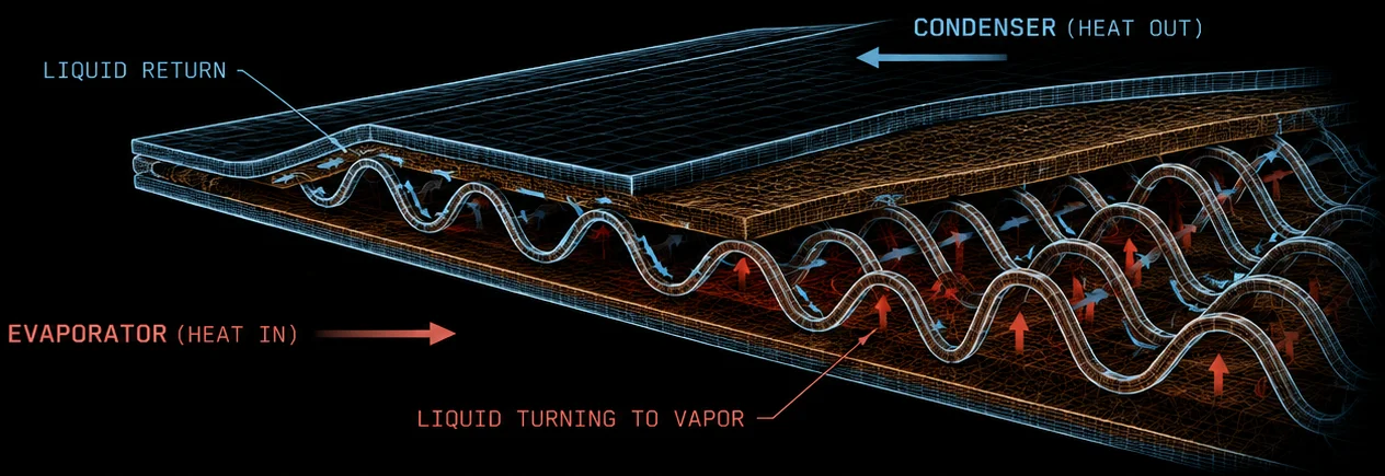
FIG. 01 — Heat pipe (left) and vapor chamber (right). Working fluid evaporates at the heat source, travels as vapor to the condenser, condenses, and returns to the evaporator — passively, with no moving parts.
Two-phase cooling is not a complete thermal solution on its own. It solves two specific problems — heat spreading and heat transport — and hands off to a downstream rejection mechanism.
STAGE 01
Processor die, RF module, power device
THE TWO-PHASE BRIDGE
Heat pipes · vapor chambers · thermosyphons
STAGE 03
Fin stack · cold plate · chassis · airflow
STAGE 04
Beyond the device boundary
FIG. 02 — Two-phase devices are the high-conductivity link between the heat source and whatever rejection method the system uses. They do not reject heat to ambient.
Moves thermal energy away from a concentrated source — like a processor die or RF module — across a larger surface area to reduce peak temperatures.
Moves that energy from the source to a remote rejection point, such as a fin stack or cold plate, where it can leave the system.
▬ Heat flow ▬ Working fluid (phase change) ▬ Airflow / rejection
What two-phase heat transfer does not do is reject heat to ambient. That step still requires a downstream mechanism: forced air across a fin array, a liquid-cooled cold plate, or a conduction path to a chassis wall. Engineers should think of heat pipes, vapor chambers, and thermosyphons as a thermal bridge — not a replacement for the rest of the cooling architecture.
This distinction matters at the design stage. Sizing a vapor chamber or heat pipe assembly correctly depends on knowing the rejection-side boundary condition. The two elements are interdependent, and both must be designed together.
Size the bridge to the rejection-side boundary condition — never in isolation.
Typically considered when local heat flux, distance, temperature uniformity, or packaging constraints limit the effectiveness of solid metal conduction or conventional cooling alone.
When heat must be moved from the source to a remote heat sink, chassis wall, cold plate, or radiator, passive two-phase devices often provide significantly lower thermal resistance than solid metal conduction.
Power density in the range of 20 to 50 W/cm² or higher, where solid metal bases cannot spread heat fast enough to prevent hot spots.
A localized heat source with a much smaller area than the available rejection surface, where spreading resistance is the dominant thermal bottleneck.
Multiple sources requiring consistent temperatures across an array, where single-phase gradients would produce unacceptable variation.
Insufficient fin area or airflow for air cooling alone, requiring heat to be moved to a remote rejection zone.
Applications where long service life, no moving parts, and zero power draw are requirements — such as sealed defense electronics or space platforms.
Send us your heat source, envelope, and rejection method — we’ll tell you straight whether two-phase earns its place.
The device types we design and manufacture. All are passive, sealed, and require no external power to operate.
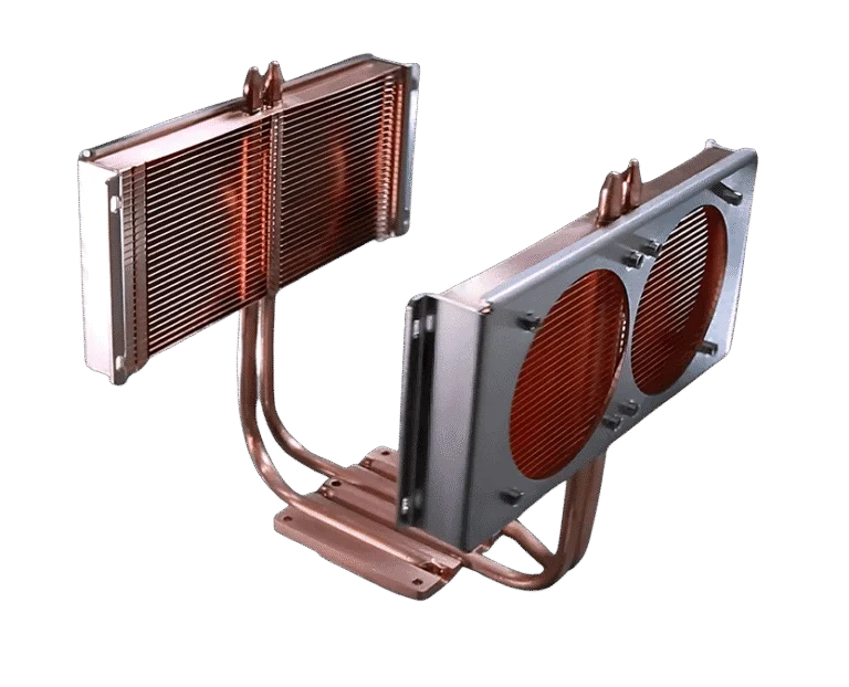
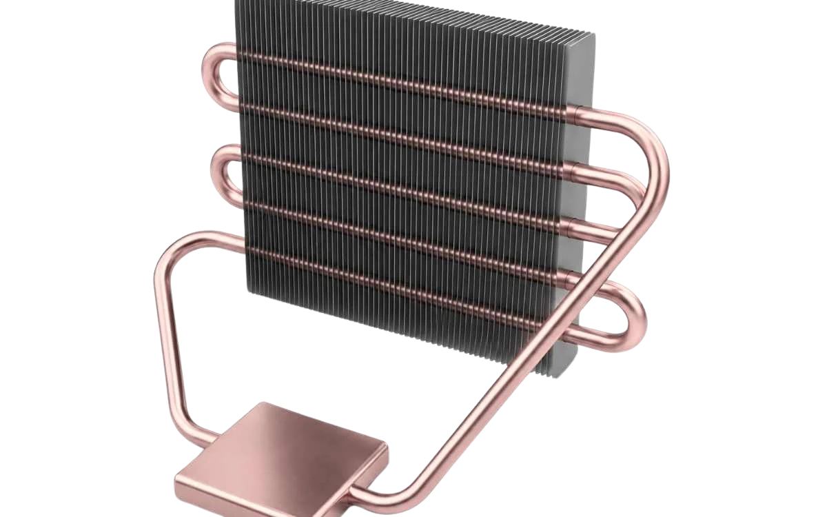
Sealed devices containing a working fluid and a wick structure inside a metal envelope. They transfer heat through evaporation at the source and condensation at the sink, with the wick returning condensate via capillary action. Typical heat pipes handle 10 to 500 watts, with high-performance sintered-wick designs exceeding 1 kW. Their ability to be bent or flattened makes them adaptable to complex mechanical envelopes.
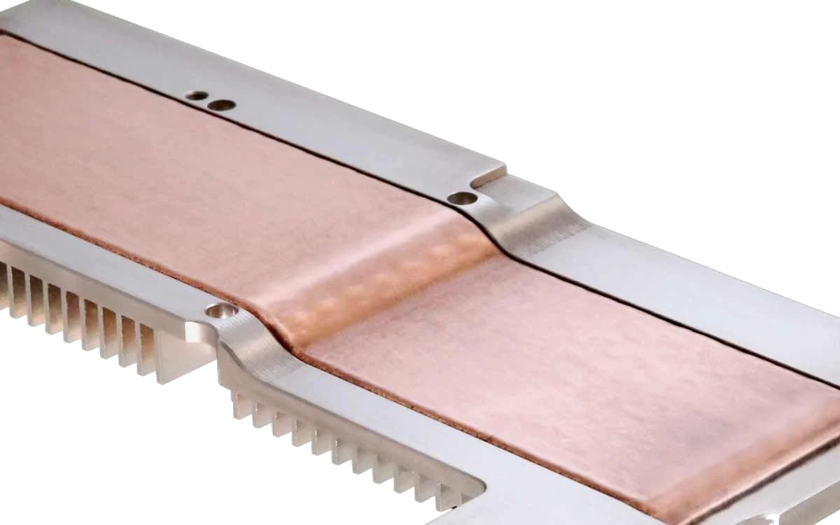
Extend heat pipe principles into a flat, planar geometry, spreading heat two-dimensionally from a localized source to a larger base area. Particularly effective at eliminating hot spots in high-power CPUs, GPUs, and RF devices, and commonly replace solid metal base plates in high-performance heat sink assemblies.
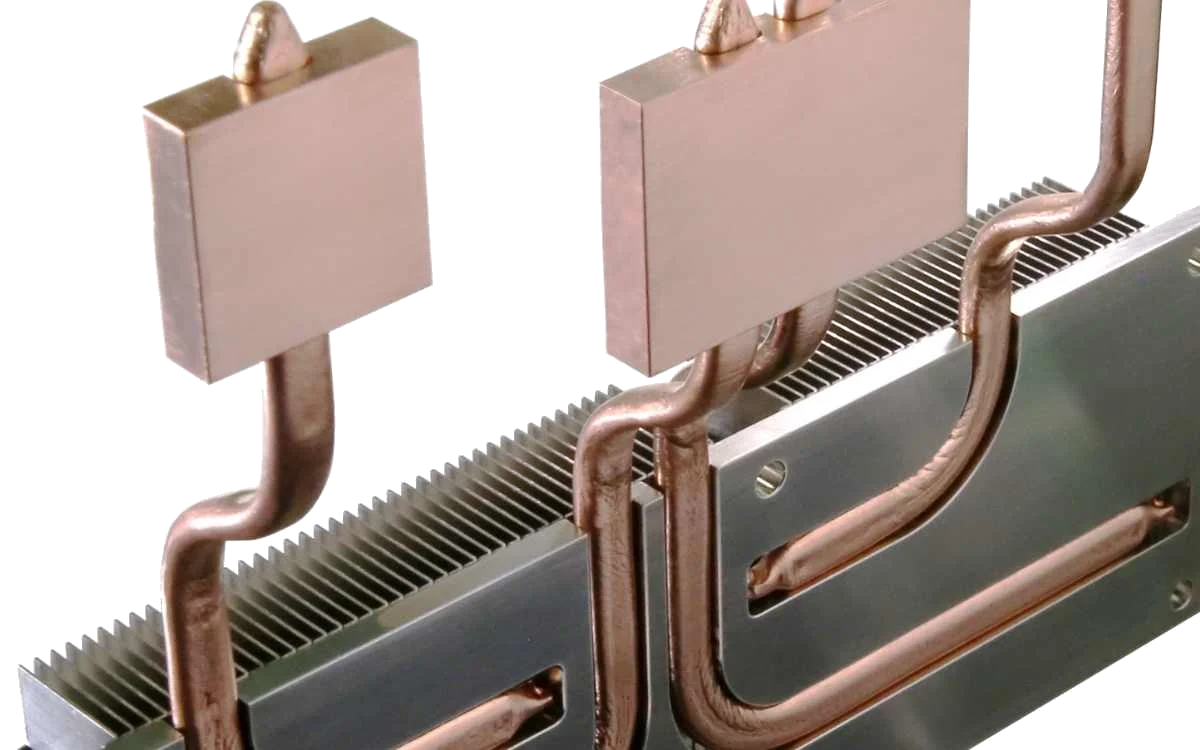
Operate on the same two-phase cycle as heat pipes but use gravity rather than capillary action to return condensate to the evaporator. The absence of a wick simplifies manufacturing and reduces cost. Well-suited for industrial and telecommunications applications where the condenser is reliably positioned above the evaporator.
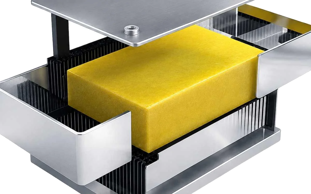
Phase change material (PCM) heat sinks absorb and temporarily store thermal energy during peak power events by melting a material with a defined transition temperature. Rather than transporting heat to a remote location like a heat pipe or thermosyphon, PCM heat sinks limit temperature rise by acting as a thermal reservoir, making them well suited for intermittent-duty applications where heat generation exceeds available cooling capacity for short periods. Because they require no pumps, controls, or moving parts, PCM heat sinks provide a reliable passive solution for aerospace, defense, medical, industrial, and portable electronic systems subject to cyclic or mission-based thermal loads.
Celsia does not design or manufacture these systems. Shown for engineers researching across the full spectrum of two-phase approaches.
NOT OFFERED BY CELSIA
A mechanical pump circulates subcooled liquid to evaporators, where partial vaporization occurs before vapor is routed to a condenser and the liquid returned. Forced circulation allows higher power densities and more precise flow control, at the cost of mechanical complexity and pump maintenance. Used in aerospace thermal control loops and high-power industrial equipment.
NOT OFFERED BY CELSIA
Submerges electronics directly in dielectric fluid, which boils at around 50°C and condenses on a heat exchanger above the tank, returning liquid to the bath passively. Used in AI and HPC data centers where rack power densities exceed what air cooling can manage — infrastructure-scale systems, distinct from component-level passive devices.
NOT OFFERED BY CELSIA
Vapor-compression refrigeration uses a compressor, condenser, and expansion valve to achieve sub-ambient cooling. Used in applications requiring temperatures below ambient, such as certain semiconductor test equipment and specialized defense systems.
Two-phase devices can provide much higher effective thermal conductivity, because vapor transport moves heat across the device with relatively low temperature drop. This is especially valuable when heat must spread from a small source to a larger heat sink footprint.
The advantage is not always bulk heat removal — single-phase liquid can reject large heat loads when flow rate, pressure drop, and cold plate area are available. Two-phase devices are often selected because they improve spreading, reduce hot spots, or move heat passively to a better rejection location.
Addressing spreading and transport problems across industries where heat flux, envelope constraints, or reliability requirements exceed what conventional air cooling can provide.
A correctly specified two-phase device lives or dies on a handful of boundary conditions — the variables our engineers model and verify on every program.
Evaporator sizing must be based on accurate source heat flux maps to avoid film boiling and the sharp drop in heat transfer coefficients that follows.
Capillary-driven devices have orientation-dependent performance limits that must be evaluated against worst-case installation and operational orientations.
Contact between the two-phase device and the heat source must be controlled for flatness and bond line thickness — interface resistance often rivals spreading resistance in its effect on junction temperature.
Working fluid purity and enclosure material compatibility must be validated to prevent non-condensable gas generation, which degrades performance over time.
Our Two-Phase Cooling Design Guide and Heat Sink Design Fundamentals cover the engineering detail behind every specification.
Active patents behind our passive phase-change designs
Testing of every two-phase device prior to shipment
Two-phase thermal management is the core of what we do. The majority of our programs involve passive phase-change designs, backed by 30+ active patents and thousands of custom assemblies delivered across aerospace, defense, telecom, and industrial markets.
Whether you are specifying a two-phase cooling device for the first time or refining an existing design, our engineering team can help you select the right approach and work through the tradeoffs.
Certified quality management with full export-control and materials compliance across every program.
Technical resources to support two-phase device selection, design guidance, and integration into high-reliability electronics systems.
Two-phase cooling and heat sink design fundamentals, selection criteria, and tradeoffs.
Worked examples across aerospace, defense, RF, and high-performance computing.
Tell us about your heat source, your envelope, and the rejection method you’re working with. We’ll help you select the right approach and work through the tradeoffs — from initial thermal analysis through prototype and production.
DEMO FORM — CONNECT TO YOUR CRM / EMAIL AFTER IMPORT
By submitting, you agree to be contacted by a Celsia engineer. ITAR-restricted technical data should be exchanged through verified secure channels after initial contact.